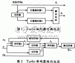
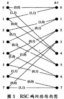
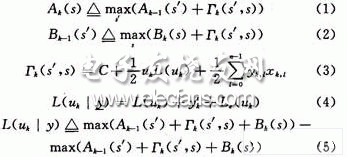
Turbo code is a major breakthrough in the field of error correction coding in communication systems in recent years. He has won the favor of many scholars for its superior performance close to the Shannon limit. In this paper, the optimization algorithm based on Max-Log-Map is used to optimize the key techniques such as state metric normalization calculation and sliding window algorithm. When the performance requirements are met, the algorithm complexity is greatly reduced. 1 Turbo encoder. Decoder and algorithm The Turbo encoder adopts the 3GPP coding scheme, and the RSC encoder with the constraint length K of 4 and the code rate of 1/2 is parallelly cascaded by one interleaver, and three decoders are respectively added to improve the performance. The tail bit causes the final state of the decoder to be all zeros. The decoder adopts a feedback iterative structure. Each stage of the decoding module includes two interleaved component decoders in addition to the interleaver; the soft decision information of the output of one component decoder is processed into an external information input. Another component decoder forms an iterative decoding and hard decision output after iterating a certain number of stages. The coded grid table runs through the entire decoding process. The RSC grid structure at any time k~k+1 is shown in Fig. 3. The 0~7 state of the encoder input in the figure can be represented by binary. The Max-Log-Map algorithm is described below. Due to the large number of multiplication operations and exponential operations required, the Map algorithm is not suitable for hardware implementation. ERFanian and Pasupanthy first proposed the simplified algorithm *og-Map algorithm for the Map algorithm in the logarithmic domain. By converting to a logarithmic domain operation, exponential operations are avoided, while multiplication becomes additive, and addition becomes Max, but this also introduces a certain performance penalty. The Max-Log-Map algorithm is briefly described below. Let Ak(s), Bk(s), Γk(s) represent the forward state metric, backward state metric and branch metric of the logarithmic domain, respectively, and their expressions can be expressed as: As shown in FIG. 3, each node state s corresponds to one Ak(s), one Bk(5), and two Γk(s). Therefore, the coding network runs through the entire coding and decoding process. Before decoding, the mesh mapping table is first established according to FIG. 2 key improvement and optimization of decoder implementation Turbo code decoding is a complicated process. The reason for this is that in addition to the complexity of the algorithm itself, there are two main reasons. One is that the pre- and inverse metrics in the recursive calculation process are increasing to the signal processor. The trouble, that is, the overflow often said; the other is the large storage demand. Here, we discuss and summarize these two details and give detailed solutions. 2.1 State metric normalization problem It can be noticed from equations (1) and (2) that as the calculation progresses, the state metric value increases continuously, and in order to prevent computational overflow and reduce hardware complexity, it must be normalized. One method is to subtract the minimum value of the state metric at the previous moment. This method requires a subtractor and a comparator for calculating the minimum value at each moment. When the number of states is large, the additional time is brought about. Deferred hardware consumption cannot be ignored. The algorithm uses a very effective normalization method (take Ak(s) as an example). At each calculation time, it is judged whether there is any state metric (A or B) greater than a certain threshold T, if any. The state metric (A or B) of all nodes is decremented by T, and if not, the original value remains unchanged. This greatly reduces the number of times the subtractor is used and does not need to calculate the minimum. Since all nodes subtract the same value, the result of equation (5) is not affected. The T value should not be set too large, but it is set too small, normalization occurs very frequently, which increases the decoding delay and hardware overhead. Through experimental simulation, if q represents the quantized word length of the state metric value, then T is set to 2q-2. 2.2 Introducing a sliding window to reduce the amount of storage Due to the iterative nature of the Turbo code decoding algorithm, each level of Map decoder requires a large amount of memory. The introduction of a sliding window during decoding can effectively reduce the amount of storage required. The Map decoding step using the sliding window is as follows: each decoding process is divided into several segments with an interval L (assuming that the length of the sliding window is L, L "N) is continuously performed, and only the data of nL length is forwarded. After processing, each reverse sub-process can be executed, and when the sliding window is not used, the entire data block needs to be processed before it can be performed. Experiments have shown that the performance of the bit error rate is almost negligible when the sliding window size is 7 to 8 times the constraint length. In this algorithm, the constraint length is 4, and the selection window size is 32. The comparison of the storage space allocation between the two algorithms before and after decoding using the sliding window is given below. Assume that the encoding frame length is L, B represents the window length, and L is an integer multiple of B. According to Table 1, this storage space is 26L, and when L=1K, it is 26K. If we use block decoding, according to Table 2, the storage requirement of the whole decoding is 20B+8L, B is generally 5 to 10 times the length of the coding constraint, and for 8 state coding, B=32, then this storage space It is 640+8L, which is much smaller than 26L of Table 1. When L=1K, the storage space only accounts for 33.2% of the original. When the encoding frame length L is taken to be larger, the storage space is more significant. Compared with the sliding window, Turbo decoding can greatly save hardware storage resources. FC Patch Cord stands for Fixed Connection. It is fixed by way of threaded barrel housing. FC connectors are generally constructed with a metal housing and are nickel-plated.FC FC Patch Cord it is composed of a fiber optic cable terminated with different connectors on the ends. FC Apc Patch Cord are used in two major application areas: computer work station to outlet and patch panels or optical cross connect distribution center.Foclink,a reliable supplier of FC Pigtail , is always beside u 7*24. We provides various types of Fiber Optic Patch Cables including single-mode, multimode, multi-core, armored patch cables, as well as fiber optic pigtails and other special patch cables. For most of the patch cables, the SC, ST, FC, LC, MU, MTRJ, E2000 connectors (APC/UPC polish) are all available. In addition, we also have MTP/MPO cables in stock. FC Patch Cord FC Patch Cord,FC FC Patch Cord,FC Apc Patch Cord Foclink Co., Ltd , http://www.scfiberpigtail.com


