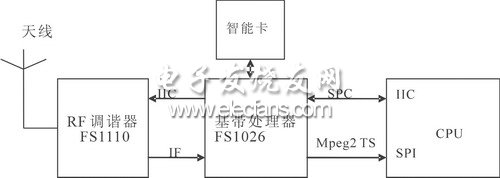
This article discusses in general terms the hardware and software development of embedded mobile devices such as mobile TV: how to design hardware, achieve audio and video synchronization, improve H.264 decoding rate, and prevent DMA buffer overflow. This article refers to the address: http:// hardware design Hardware design overview The choice of hardware configuration should be considered comprehensively, such as the processing function of the CPU is related to the final decoding display effect. Of course, choosing some high-end general-purpose processors, or dedicated media processors, can achieve better results, but it increases the cost of hardware. A compromise can be made in the final display and hardware selection. At present, there are not many chips that can receive T-DMB and DVB-H standards, and some mainstream chips on the market can be selected. The hardware configuration of this product discussed in this article is: S3C2440A (400MHz), 64MB SDRAM, apollo fs1110, kino2efs1026. Basically can meet the hardware needs of mobile TV. The RF signal received by the antenna is sent to the RF tuning chip APOLLO FS1110 of the RF front end, and the main function is to demodulate the RF signal into an IF (Intermediate Frequency) signal. This chip is currently the mainstream product on the market, can receive multiple standard signals, and is small (5.0mmx5.0mmx0.9mm), low power consumption (80mW), with three low noise front-end amplifiers, covering L-Band , BandII and BandIII three bands. Apollo fs1110 sends the IF signal to kino2 efs1026, and completes the source code decoding output MPEG2-TS data. Kino2 is a highly optimized baseband processor with small size (10mm x 10mm x 1.3mm) and low power consumption (100mW). It can provide various DMB bit rates up to 1.8Mbps. It has an RS decoder on the chip. Achieve better mobile channel performance. Kino2 sends the source code TS code stream to the CPU, and the CPU completes the demultiplexing, decoding and display of the TS stream. The hardware design block diagram is shown in Figure 1. Figure 1 hardware design block diagram Hardware function module description Mobile TV terminals will eventually support multi-standard and multi-band, which is also the market demand. Since the frequency bands used in the three mobile TV services are not the same, such as Beijing and Guangdong adopting VHF Band 3, and Shanghai adopts L-Band, the same mobile TV terminal should receive mobile phone services in different regions of China. Need to support multiple frequency bands. The T-DMB discussed in this paper uses the VHF band 3 and the L band. Therefore, BandIII and L-Band of the FS1110 are used; BandII is mainly used for FM broadcasting. The three high-frequency inputs of the FS1110 can be used. The band selection can be controlled by the FS1026 through the IIC interface. At the same time, the initialization of the FS1110 internal registers is also done through this interface. The downstream FS1026 baseband processor module receives the IF signal sent by the RF tuner and finally completes the source decoding. The output MPEG2-TS data supports both parallel and serial formats. Serial data can be directly connected to the CPU via the SPI interface. The baseband module can also exchange control information through the SCP (Serial Control Port) interface and the CPU. The SCP interface and the IIC interface are fully compatible. It is also possible to communicate with the CPU using a serial port (UART). Since some commercial DMB programs are scrambled (encrypted) by the service provider, the smart card module can perform the descrambling function. The function of the CPU is to receive the TS data through the SPI interface and complete the decoding of the audio and video. Data can be cached by DMA and then read from the DMA for demultiplexing. DMA mode is a high-speed data transfer operation that allows direct reading and writing of data between external devices and memory, neither by the CPU nor by CPU intervention. The entire data transfer operation is performed under the control of the DMA controller. In addition to doing a bit of processing at the beginning and end of the data transfer, the CPU can perform other tasks during the transfer. Thus, most of the time, the CPU and input/output are in parallel operation. Therefore, the efficiency of the entire system can be greatly improved. Under the WinCE platform, the operation of the DMA is quite convenient, and the driver development is not difficult. Reading data is just like operating a normal file. The only difference is to prevent DMA overflow. Because the reading of ordinary files is completely controllable, and here is a "real-time" stream, overflow may occur. Overflows include overflow (data read too slow) and underflow (read too fast). The principle of preventing data overflow from the decoder receiving end of MPEG is the same, mainly because the format of the image encoding is different, and the data rate of the transmitted decoder front end is not constant. MPEG uses flow rate feedback control to control data overflow so that the data rate to the audio and video decoder tends to be constant. The control of the DMA is simpler. The data is read by a dedicated thread. The demultiplexing thread can discard certain frames or slow down the decoding speed depending on the amount of data. However, there are still many cases where frames are dropped. Hardware design considerations The main problem when designing the hardware circuit is high frequency and electromagnetic compatibility. The general method is to add a shield. The APOLLO FS1110 can be shielded to reduce the space interference of the module. Of course, APOLLO FS1110 and KINO2EFS1026 can also be made into external modules. It is also possible to reduce the effects of high frequencies by optimizing the design of the schematic. Because the quality of the schematic directly affects the layout, the difficulty of wiring, and the performance of the board in the future. In order to clearly and clearly partition the layout for layout, to reduce the impact between the various functional modules, the digital, analog and RF circuits should be separated when designing the schematic. However, shields are generally indispensable due to the small size of the handheld device. software design Overview of the T-DMB standard The T-DMB adopts the H.264 video compression standard, and the audio is MPEG-4 bit-sliced ​​arithmetic coding BSAC (Bit-Sliced ​​Arithmetic Coding) or AAC+ (European T-DMB). The image format is CIF (Common). Intermediate Format) (352 × 288), add some user data to these audio and video streams, and multiplex them by MPEG-4 SL (Sync Layer) synchronization layer and MPEG-2 TS (Transport Stream). The modulation is transmitted as a signal suitable for propagation over the channel. The receivers of various standards have a large difference in channel decoding, and the decoding of the sources is very similar. The structure of the transmitter encoder of the T-DMB system is shown in Figure 2. Figure 2 T-DMB transmitter coding block diagram The MPEG-4 OD/BINFS generator generates audiovisual objects, scene spatiotemporal relationship information, and descriptor information of the audiovisual objects. The IOD generator generates initial information of the audiovisual object: a scene description and object description information. The segmentation generator mainly collects SLP and IOD data information for generating reference information PSI (Program Specific Information) related to program demultiplexing. In the data stream of the T-DMB, the IOD_descriptor can be obtained by parsing the description field in the PMT, and the scene and object description information can be obtained by the IOD_descriptor. Information such as ES_descriptor can be obtained from the object description. The SL synchronous packer is mainly responsible for synchronizing audiovisual objects and auxiliary data. After the SL packet is packaged by the PES, the PES packet is sent to the modulator as a TS packet. Functional description of the software The main tasks of the software are demultiplexing of TS streams, decoding of H.264 and AAC+, and development using Microsoft Direct Show technology, which can reduce development difficulty and development cycle. Direct Show technology is a Windows platform multimedia development kit provided by Microsoft, based on COM. Direct Show uses the Model of Filter Graph to manage the processing of the entire data stream. The various functional modules involved in the processing are called Filter, which are divided into three categories according to functions: Source, Transform, and Rendering Filter. Source Filter is mainly responsible for obtaining data and pre-processing; Transform Filter is responsible for data format conversion and transmission, mainly responsible for decoding; Render Filter is responsible for display. The interaction between each Filter and the application is done by an event notification mechanism: an event is emitted when the Filter state changes, and is processed by the Filter Graph Manager or sent to the application. The entire software can be divided into five major functional modules, as shown in Figure 3. The TS demultiplexer module belongs to the Source Filter, which is used to obtain data from the DMA buffer, and then parse the PAT (Program Association Table) and the PMT (Program Map Table) from the TS stream to obtain the audio and video data TS packets of the related programs. After the PID (Packet Identifier), the PES (Packetized Elementary Stream) packet can be combined, and parameters related to audio and video synchronization can also be obtained: PCR (Program Clock Reference), CTS (Presentation Time Stamp), and DTS (Decoding Time Stamp). Finally, the ES (Elementary Stream) data after the PES packet is removed from the packet header is sent to the downstream decoding Filter. The H.264 and AAC+ decoding modules belong to the Transform Filter. The main function is to decode the audio and video data acquired from the upstream, and reorder the decoded PU (Presentation Unit) (only need to sort when using bidirectional prediction). The downstream generator. The Video Generator and Audio Generator modules are part of the Rendering Filter and are primarily used for display. If the data format needs to be converted, you can add a Transform Filter with conversion function between the decoder and the generator. Audio and video synchronization The key technology in software design is to solve the problem of audio and video synchronization. Audio and video synchronization is mainly solved in the TS demultiplexer. To synchronize audio and video, you need to use these parameters: PCR, DTS, PTS. The PCR can be obtained in the adjustment domain of the TS packet, and the PTS is obtained from the PES packet. The data in the PES packet is the SL packet, and the DTS can be obtained from the SL header. DTS is the decoding time and PTS is the display time. The PCR is a count of the encoder 90K clock, which is used to provide an initial value to the decoder PCR counter when the decoder switches programs. The PTS and DTS are most likely to reach the same starting point of time as the PCR, that is, provide a common clock reference to the decoder for accurate audio and video synchronization. Audio and video decoding can be performed when the PCR captures the same time as the DTS value. Because the video coding uses bidirectional prediction, an image unit is not immediately displayed after being solved, and may remain in the memory for a period of time, as a decoding reference for the remaining image units, and is displayed after being referenced. Since the sound does not use bidirectional prediction, its decoding order is its display order, so it only proposes the concept of PTS for MPEG, and PTS is the DTS value of audio. which is: DTS=PTS (1) If PTS is not available, then calculate as follows: PTS=PTS_pre +Xms (2) Where PTS_pre represents the PTS of the previous AU, and X is the time interval of ACC+ one frame, in units of ms. The general video object is divided into three coding types: I-VOP, B-VOP, and P-VOP. Assume that the VO (Video Object) input order at the decoder side is: 1 2 3 4 5 6 7 8 9 10......... IBBPBBPBBPBBPBBIBB P....... Since the video object is encoded using bidirectional prediction, the actual decoding order of the decoder is: IPBBPBBPBBPBBIBBPBB ....... The display order is the same as the input order of the decoder. Assume that the PTS and DTS of the I frame are known. Then get about the P frame: PTS_P4=PTS_I +33.67ms * 3 (3) DTS_P4=DTS_I +33.67ms (4) B1 frame: PTS_Bn=PTS_I +33.67ms * 2 (5) DTS_Bn=DTS_I +33.67ms (6) The B2 frame can refer to the above two equations. Among them, 33.67ms is the video frame time interval. Software development considerations Regarding the decoding efficiency of H.264. The software decoding part uses the H.264 decoder in the open source project ffmpeg, which is highly efficient and easy to transplant. Among them, key operations such as IDCT and motion compensation are also implemented in assembly on several different platforms. Porting the H.264 decoder to the ARM platform, IDCT and motion compensation assembly code can be implemented just like the code of other platforms, and its development is not difficult. The audio decoding part can refer to the FAAC and FAAD open source projects. Conclusion This paper discusses an overview of the hardware and software design of an embedded handheld device that can receive mobile TV signals that conform to the T-DMB specification (with very different receiving terminals for various standards). This device allows users to obtain directly without going through a mobile communication network. Digital TV signals can meet people's needs for information anytime, anywhere. The main hardware problem in the actual development process is electromagnetic compatibility. The software is the synchronization of audio and video and the decoding efficiency of H.264. The difficulty of software development focuses on the design of MPEG-2 demultiplexing and Direct Show application frameworks. Water Block is a heat-absorbing device of water cooling system. The water block is attached to the chip closely. Absorbing the heat emitted by the chip at any time to achieve the effect of heat transfer.Water block also has CPU Water Block and Gpu Water Block these two types, respectively bear the heat transfer function of the two.The water block is made of red copper, because the thermal conductivity of copper is better than other metals, and the price is moderate, which is the ideal material for water block.There are tiny channels inside the water block, and the water flow takes away heat quickly and ensures the normal work of the chip. Water Block Water Block,Acrylic Copper Water Block,Liquid Cooling Water Block,Copper Cpu Water Block Dongyuan Syscooling Technology Co., Ltd. , https://www.syscooling.com