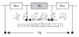
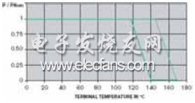
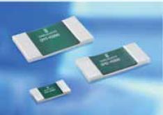
In the past few years, the practical application of small-volume high-precision and low-resistance resistors, as well as the significant increase in data acquisition and processor performance, have led to technological innovations in traditional shunt-based current sensing methods. New applications became possible, which was unimaginable a decade ago. This article refers to the address: http:// The operating current of the body electronic control system is mostly between 1-100A. In special cases (such as oxygen sensor heating), there will be a short-time 200-300A current, and the starting current of the vehicle is even as high as 1500A. In battery and power management systems, there are more extreme cases where the vehicle is running with a continuous current of 100-300A, while at rest, the current is only a few milliamps, which needs to be accurately detected. Fundamental According to Ohm's law, when the current being measured flows through the resistor, the voltage across the resistor is proportional to the current. This design is not problematic when the current through the 1W resistor is several hundred milliamperes. However, if the current reaches 10-20A, the situation is completely different, because the power lost in the resistance (P = I2xR) can not be ignored. We can reduce the power loss by lowering the resistance value, but the voltage across the resistor will also be reduced accordingly, so the resistance of the resistor should not be too low based on the sampling resolution. In general, the following formula applies to calculating the voltage across the resistor: U=RxI+Uth+Uind +Uiext+...... Uth is the thermoelectromotive force, Uind is the induced voltage, and Uiext is the voltage drop caused by the tiny current on the PCB lead. The error voltage caused by the current-independent factors can directly affect the accuracy of the measurement, so the designer should understand these factors and reduce the related effects through careful board layout, especially selecting the appropriate components. A wide variety of conductive materials can be used to make resistors, but such components are not well suited for current sampling. Because the resistance is related to parameters such as temperature, time, voltage and frequency, R = R (T, t, P, Hz, U, A, m, p, ...). Table 1 The actual resistance performance is more or less related to its base material and production process. The ideal current sense resistor should be completely independent of these parameters, although such resistors do not exist. The actual resistance characteristics are shown in Table 1, including temperature coefficient TCR, long-term stability, thermoelectromotive force, load capacity, inductance and linearity. Some of the characteristics are determined by the material itself; some characteristics are determined by the component design, and some parameters are determined by Production process. As early as 1889, Isabellenhuette of Germany invented the precision resistance alloy Manganin, whose excellent properties laid the foundation for precision measurement technology. Later, the company invented Isaohm and Zeranin with their resistivity of 132mW xcm respectively. And 29mW xcm, the family of resistance alloys is perfect, all of these alloys have greatly met the global demand for resistive materials and have long been successfully applied by precision resistor manufacturers. In the past 25 years, in response to the development of magnetic field-based current sensing methods, Isabellenhuette is committed to extending the current sensing range of the shunt by physically optimizing the shunt resistor. At the same time, semiconductor companies have improved many of the op amp's features such as drift, temperature coefficient and noise, which has enabled electronics engineers to use milliohm-rated shunt resistors in their designs to solve high power losses at high currents. problem. However, the attendant price is that the correlation error caused by interference and thermoelectric effects is also greatly increased, so it is particularly important to reduce the parasitic inductance and suppress the thermoelectromotive force. Temperature Coefficient Figure 1 is a typical temperature characteristic curve of a manganese-nickel-copper alloy resistor. The temperature coefficient TCR is in ppm/K. At 20 or 25 °C, TCR=[R(T)-R(T0)]/R(T0) ×( T-T0), for the definition of the temperature coefficient, it is necessary to manufacture the upper limit of the temperature of the trademark. For example, in the temperature range of +20 - +60 °C, the measurement system often uses a low resistance of TCR of several hundred ppm/K. Value of the thick film resistor, the red curve in Figure 1 shows the temperature characteristics of the resistor with a TCR of 200 ppm/K. Even in such a small range, a temperature change of +50 °C is enough to cause the resistance to change by more than 1%. Such resistors cannot be used for accurate current measurements. Some measurement equipment manufacturers even use copper traces of PCB traces as current sense resistors. The TCR of copper is 4000 ppm/K (or 0.4%/K) and the temperature is 2.5 °C. The change is enough to cause a 1% error. Fig.1 Typical temperature characteristic curve of manganese-nickel-copper alloy resistor Thermoelectromotive force When the temperature rises slightly or decreases, a thermoelectric potential is generated at the contact surface of different materials. This effect is very important for the low resistance resistance, although the thermoelectric potential value is usually very small, but the microvolt-level thermoelectricity The potential can seriously affect the measurement results. To this day, the resistance alloy Constantan is still the main material for the winding and stamping shunts (molding on sheet materials), and although it has a good TCR, its thermoelectric potential for copper is as high as 40 mV/K. For example, using a 1 milliohm shunt resistor to sense a 4A current, a 10°C temperature difference produces a voltage difference of 400mV, which is equivalent to a 10% increase in measurement error. More seriously, if the resistance size is taken into account, the often neglected Peltier effect can increase the temperature difference above 20 °C by mutual heating or cooling between the contact surfaces (very extreme example). It is the melting of the welded part). Even if the circuit under test operates in a constant current state, the temperature difference due to the Peltier effect causes a voltage to exist and the display current is not constant. After the current is turned off, the measurement results show that there is a significant current before the temperature difference disappears. The current error can be several percentage points or several amps depending on the design and resistance. The thermoelectric properties of the precision resistor alloy mentioned above are very close to that of copper. The metal and metal contact surfaces do not generate thermal voltage, and the designer can even ignore the Peltier effect. For example, using a 0.3mW resistor, the generated thermal voltage is less than 1mV. When the 100A current is turned off, the thermoelectric potential produces less than 3mA. Long-term stability is very important for any sensor. Even after a few years of use, people hope to maintain early accuracy. This means that the resistive material must be corrosion resistant during the life cycle and the alloy composition cannot be changed. In order for the measuring component to meet these requirements, an alloy composed of a homogeneous composite crystal can be used to achieve a basic thermodynamic state through an annealing and stabilization process. The stability of such alloys can be on the order of ppm/year, making them suitable for standard resistance. Figure 2 is a typical long-term stability curve of surface mount resistors. It can be seen that the resistance is only about -0.2% slight drift after 1000 hours of aging at 140 °C, which is due to slight deformation during production. Caused. The resistance drift is largely determined by the high temperature, so at lower temperatures such as +100 ° C, this drift is actually not detectable. Figure 2 Typical long-term stability curve of surface mount resistors Four terminal connection In low-resistance resistors, the influence of the resistance and temperature coefficient of the terminals is often not negligible. These factors should be fully considered in the actual design. The voltage across the metal material can be directly measured using additional sampling terminals. As shown in Figure 3, a four-terminal connection will allow the measurement system to actually use a value of R0, while the normal connection has a resistance of R0+2xRCu. For example, a copper wire with a diameter of 10 mm and a diameter of 0.3 mm will increase the RCu resistance of 2.4 mW, and a RCu resistance of a PCB lead of 4 mm long, 0.2 mm wide and 35 mm thick is 10 mW. Figure 3. A four-terminal connection will allow the measurement system to actually use a value of R0. The resistance of a normal connection is R0+2xRCu These examples show that defective resistor structures or unreasonable wiring can cause very large errors. For a 10 milliohm two-terminal resistor, the copper connection line accounts for 24% of the total resistance, and even a short 4mm PCB layout has been Double the resistance. The bonding surface cleaning process of the resistive material and the copper terminal before soldering can reduce the additional resistance of the terminal, but the influence of the TCR still exists. In the example depicted in Figure 4, the proportion of copper is as small as 2% (compared to the previous 24% example), whereas the TCR is increased from near zero to 80 ppm/K. For a low-resistance resistor of such a structure, it is of no value if the TCR of the alloy material itself is only listed in the technical document. Figure 4 Four-terminal connection allows the measurement system to directly acquire signals from highly reliable sensing elements The copper-manganese-nickel-copper resistor by electron beam welding actually has such a low terminal resistance value, and can be used as a two-terminal resistor by a reasonable wiring to approach the performance of the four-terminal connection. However, it must be noted that the signal connection of the sampling voltage must not be directly connected to the current path of the sampling resistor. If possible, it is better to connect the current terminal from the underside of the sampling resistor and design it as a microstrip line. High load power Since the thermal conductivity of the resistive material is worse than that of copper, and most of the resistors use an alloy foil of an etched structure having a thickness of between 20 and 150 mm, heat cannot be dissipated through the resistive material to the terminals. One of the solutions is to bond the resistive alloy foil to a substrate material (copper or aluminum) that also has good thermal conductivity with a thin, thermally conductive adhesive. This structure effectively conducts heat to the surrounding environment, ensuring that the resistor has a very low thermal internal resistance (typically 10-30K/W). (The resistors of the ISA-PLAN series are manufactured using this technology, translator's note) The resistance of this structure can work at full load at very high temperatures, as shown in Figure 5, at a very high temperature, the power reduction occurs; at the same time, the temperature of the resistive material can be maintained at a low level, which can be effective Improve the long-term stability of the resistor and the change in resistance due to temperature. Figure 5: Due to its low thermal internal resistance, power reduction occurs only at high temperatures. For extremely low resistance resistors using composite structures, the cross-sectional area and mechanical strength of the resistive alloy are large, so it is not necessary to use the backplane, which means that the resistive material has a sufficiently low thermal internal resistance, for example 1 mA European resistance, thermal internal resistance is about 10K / W, but 100 micro ohms resistance, thermal internal resistance is only 1K / W. Low inductance In many applications today, it is necessary to measure and control high frequency currents, and the parasitic inductance parameters of the shunts have also been greatly improved. The special low-inductance planar design of the surface mount resistors and the diamagnetic properties of the alloy material, the metal backplane, and the four-lead connections all reduce the parasitic inductance of the resistor. However, the sampling terminal and the resistor on the circuit board form a ring structure. In order to avoid the induced voltage formed by the magnetic field generated by the current and the peripheral magnetic field, it is necessary to emphasize that the area where the sampled signal line is formed is as small as possible. Ideally, the microstrip line design (see the green line in Figure 6). For example, the two sampled signal lines connected to the amplifier should be designed as close as possible or preferably routed parallel between different layers of the PCB, the worst. The result of the design (see the red line in Figure 6) is that the antenna effect will far outweigh the actual inductance of the resistor itself. Figure 6. The four-terminal connected circuit forms an antenna loop that is sensitive to the induced voltage generated by EMI. Low resistance The four-lead design is recommended for high current and low resistance applications. The usual practice is to stamp directly into a resistor using a manganese-nickel-copper ribbon (Figure 7), but this is not the best approach. Although the four-lead resistor is advantageous for improving temperature characteristics and thermal voltage, the total resistance is sometimes 2 to 3 times higher than the actual resistance, which causes unacceptable power loss and temperature rise. In addition, the resistive material is difficult to connect to copper by screws or soldering, which also increases contact resistance and causes greater losses. Figure 7: Direct stamping into a resistor with a manganese-nickel-copper alloy strip In the method of Figure 8, the use of composite stamping resistors greatly reduces errors, and the increase in total resistance is reduced to less than 10%. Designers can also use approved copper-copper bonding techniques for soldering. Figure 8 Stamping resistors with composite materials will greatly reduce the error Automotive application note For reasons of cost and miniaturization, the detection of currents below 100A in automotive electronics is increasingly using precision sampling resistors in SMD packages with resistance requirements as low as 300 microohms. In automotive electronics applications, Isabellenhuette can provide SMx. , LMx, VMx and BVx series products, all of which use a two-terminal design and optimized physical structure, choose a reasonable PCB layout, two-lead design can completely eliminate the influence of terminal and solder joint contact resistance and reach four leads Detection accuracy. For current sensing in fuel direct injection systems, gearbox control, headlight control, window control and engine management modules, a rational architecture that uses copper substrates for heat dissipation and electrical connections, perfectly adhering to manganese-nickel-copper alloys Excellent characteristics, very high continuous and pulse power, inductance value below 0.1nH, resistance range of 5 mW~5W, standard form factor from 1206, 2010, 2512 to 2817, load capacity of 0.5~3W, up to 0.5% accuracy and thermal internal resistance down to 13 K/W. The flip-chip series of two-lead design provides resistance values ​​as low as 1mW. When the resistance is less than 3mW, this design does not use a substrate. For higher resistance, an insulating aluminum substrate is overlaid as a carrier and Heat transfer medium. The resistance of this series is from 1 mW to 0.5W, the package size is 2512, 2010, 1206 and 0805. When the accuracy is 1.0%, the load is from 2W to 0.25W, and the thermal internal resistance can be as low as 15K/W. It is widely used in ignition control modules, transmission control, engine management modules, window regulators, etc. Typical applications include switching current regulators and PWM power controllers with special requirements, such as radiator fans with a maximum operating current of 100A; fans operating at an ambient temperature of +140 °C; electronic oil pumps that require operation at EMV Level 5 or Applications such as electronic water pumps with a working efficiency of 94 to 98% require motor protection and surface mount resistors. Alloy resistors made with ISA-WELD technology for PCB, DCB, MIS substrates or applications with lead-frame bonding, resistance values ​​from 100mW to 4 mW, rated power up to 5W at 1% accuracy, thermal internal resistance As low as 2K/W. data collection system There is an increasing demand for an application in automotive electronics that requires large dynamic, high-precision and high-resolution measurements of currents of hundreds of amps or even thousands of amps, while requiring extremely high currents for milliamps. Measurement accuracy and resolution, such as battery and power management systems for passenger cars, trucks and hybrid vehicles. ISA-ASIC is the solution for this application, including a complete 4-channel data acquisition system with 16-bit resolution and many special features, a data converter that does not require compensation, and composite Low-resistance shunt resistors made of materials form a near-ideal current sensor. On the one hand, it can measure currents up to 1500 amps in real time, linearly, with large dynamics and with high precision, and on the other hand, it can achieve resolutions of a few milliamps at low sampling rates. The ISA-ASIC requires only a single ±5V/3mA supply to operate. The signal under test can be bipolar or even lower than the supply voltage. In addition to measuring current, it can simultaneously measure temperature and voltage. ISA-ASIC is the best choice for current automotive battery and power management systems. With a special 2mW resistor, the ASIC system can measure continuous currents up to 10,000A with a resolution of less than 1A. The superior performance of ISA-ASIC far exceeds the expectations of engineers. Industrial Gigabit Ethernet POE Switch is an Industrial Fast Ethernet Switch with ports, supporting 10/100BASE-T ports. Industrial Gigabit Ethernet POE Switch Industrial Gigabit Ethernet POE Switch,Industrial Gigabit POE Switch,Industrial Gigabit Ethernet Switch,Industrial Gigabit Switch POE,Industrial Unmanaged Gigabit POE Ethernet switch, Industrial 10/100/1000M POE Switch Shenzhen N-net Technology Co.,Ltd , http://www.nnetswitch.com

Long-term stability 


industrial gigabit Ethernet POE Switch series is packaged in a compact IP40 case that allows either DIN rail or panel mounting for efficient usage of cabinet space.
industrial gigabit Ethernet POE switch series can support ports POE function (Optional), powering PD like HD IP Camera, wireless AP, IP phone and so on.