introduction The Chinese character NAVTEX receiver is a device that is tuned at 490/518 kHz and can automatically receive and print two forms of navigation warning, weather information and emergency information. It is a type of radio equipment that ships must be equipped under the Convention for the Safety of Life at Sea. The current NAVTEX system receiving function is mainly completed by the hardware circuit composed of analog devices, and the receiver is limited by the volume, the filter is few, the anti-interference resolution performance is quite limited, and the narrowband interference in the working frequency band is powerless, the analog circuit Unusually complex, it is difficult to improve the performance of the device and enhance the functionality of the device. The design of a new DSP-based NAVTEX receiver is presented here. Using DSP technology and software radio technology, digital filtering demodulation and self-test functions are realized, which can easily improve the performance of the device and enhance the function of the device. The algorithm research, DSP implementation and experimental results are carried out in detail. NAVTEX receiver working principle and signal characteristics Signal characteristics How the receiver works The Chinese character NAVTEX receiver includes the receiving antenna, RF receiving unit, information processing unit, printing unit, display unit and power supply. Its principle block diagram is shown in Figure 1. Design of the new NAVTEX system receiver The design mainly improves the RF receiving unit of the receiver, digitizes it, makes the circuit simple, and can conveniently improve the performance of the device and improve the function of the device. The analog circuits of the currently used NAVTEX receivers are extremely complex, and the required accuracy is such that the receiver takes up too much volume and it is difficult to achieve performance improvements and new functions. This design makes the NAVTEX receiver compact, modular, digital, and software. The design of the analog front end and information processing unit is the same as the current NAVTEX receiver, and is not mentioned here. Algorithm implementation In this design, the generation of the self-test signal can be completed in the interrupt, and the filtering and demodulation are completed in the main program. The flow chart of the main program is shown in Figure 3. Input signal generation during self-test The self-test input signal is 2FSK signal, that is, frequency shift keying. Its basic principle is: Send signal cosω1t when the transmitted data is 0, and send cosω2t when the transmitted data is 1. So the key to generating a self-test signal is to produce a sinusoidal P cosine waveform. Here, a digital oscillator is used to generate a sinusoidal signal in an iterative manner. The principle is relatively simple and will not be detailed here. A USB Phone Charger is a compact phone charger with USB port/ports and pluggable USB cable. For this kind of USB charger adapter, you can also charge your ipad/camera/bluetooth speaker/power bank,etc, with your own USB cable,it's super convenience. There are 1-USB charger, 2-USB charger,3-USB charger,4-USB charger,5-USB charger,6-USB charger, allow you to charge more than one USB device. USB Phone Charger USB Phone Charger,Mini USB Phone Charger,USB Portable Phone Travel Charger,Single USB Phone Charger Shenzhen Juyuanhai Electronic Co., Ltd. , https://www.powersupplycn.com
The frequency bands used in the NAVTEX system communication line are medium wave (518 kHz and 490 kHz) or medium and short wave (4 209. 5 kHz). It first performs 2FSK to convert the data signal into an audio signal, and its center frequency is 117 kHz. When the input data is high level, the frequency of the 2FSK signal is 1.615 kHz, and vice versa, the frequency of the 2FSK signal is 1.785 kHz. This audio signal is then used to modulate the 490 kHz (or other frequency) radio and transmit it over the wireless channel to the receiver. In the transmission process, information is affected by channel fading on the one hand and noise interference on the other hand. The performance of communication performance depends largely on the performance of the receiver, and the channel characteristics are not ideal and the presence of noise in the channel is largely directly applied to the receiving end. 
After the signal is received by the antenna, it is sent to the RF receiving unit, and the signal is demodulated at the RF receiving unit. The demodulated digital signal is sent to the information processing unit. The error correction coding, decoding and other functions are completed in the information processing unit. It is then printed by the printing unit. The response of the operating process is implemented by the display unit.
hardware design:
When transferring the NAVTEX information of a Chinese character, it is usually transmitted at a frequency of 490 kHz or 4 209. 5 kHz, while the English NAVTEX information carrier frequency is 518 kHz. For 490kHz and 518kHz signals can be directly received and sent to the DSP for processing by APD conversion. For medium and short waves of 4 209. 5kHz frequency, first downconvert to 490kHz, and then do the same.
The hardware design mainly includes analog front end design, APD conversion, DSP processing unit, control unit and information processing unit. The main block diagram is shown in Figure 2. 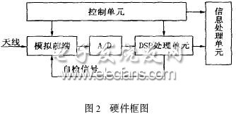
The DSP processing unit is the key to the design of the new NAVTEX receiver. It receives the control commands from the control unit and then performs matched filtering, amplification, channel filtering, channel equalization, timing extraction, and demodulation. A self-test signal is also generated to complete the self-test function. Channel noise is an important factor affecting the bit error rate of the receiver. Matching and filtering the digital signal at the receiving end can make the signal-to-noise ratio optimal. Timing extraction and carrier recovery are the most critical parts of the receiver. It mainly completes the acquisition of the best sampling points, tracking the frequency difference of the transmitted and received symbols, acquiring the frequency of the frequency wave and adjusting the phase difference of the carrier. It can be implemented here using a digital phase locked loop. Due to the nonlinear distortion and linear distortion of the channel, an equalizer is required in the receiver to compensate for the distorted channel. A self-test signal of 2FSK is generated in the DSP processing unit to complete the self-test function and verify whether the receiving channel of the receiver works normally. The current self-test circuit is mainly composed of 74HC4060 and peripheral circuits. Here, the self-test signal is generated directly in the DSP, and then the control unit decides whether to send back the input terminal for self-test, and completes the self-test function. The input signal is demodulated and output to the information processing unit to end the signal receiving process. 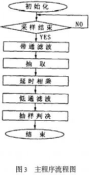
In order to complete the signal reception, multiple functions such as filtering, demodulating, amplifying, and generating an input signal during self-test are required. Because it is limited by the speed of DSP operation, it must have a computationally efficient algorithm that the DSP can run in real time.