1 Introduction This article refers to the address: http:// With the rapid development of Internet technology and multimedia technology, the application of voice communication technology has become more and more extensive, and it has received more and more attention [1]. Today's embedded devices are becoming more and more complex, with more features and higher performance than before. In a variety of embedded terminal products, audio processing functions have become an indispensable and important part, and high-quality sound is an important trend in current development. This paper designs an embedded audio system using ATMEL's AT91RM9200 microprocessor and Philips' UDA1341 stereo audio codec. The embedded audio system hardware part adopts the audio system architecture based on IIS bus, and its main hardware circuit is introduced in detail later. In software, the author uses the embedded Linux operating system as a platform to focus on the implementation of the driver of the audio system under this platform. 2 AT91RM9200 processor introduction The AT91RM9200 is a new microprocessor based on the ARM920T core introduced by ATMEL for system control and communication [2]. It has great advantages in high performance and low power consumption, and has a high frequency and can reach up to 180 MHz. The processor has independent 16K instructions and 16K data cache, full-featured MMU virtual memory management unit, and internal 16KB SRAM and 128KB ROM, EBI interface controller. On-chip integration of a wealth of peripheral interfaces, including network MAC, USB controller, SDRAM controller, CF interface, NAND flash interface, IIC interface, JTAG debugger and support 256 MB of address space. Moreover, the processor also provides a bootstrapping mode for the user to write the boot code to facilitate the porting of operating systems such as Linux. 3 UDA1341TS audio chip and IIS bus introduction PHILIPS' UDA1341TS is a powerful dedicated voice processing chip [3]. The chip integrates functions such as voice amplification, filtering, sampling, A/D and D/A conversion, and can perform digital voice processing. The AT91RM9200 processor used in this design has an IIS audio interface that uses DMA to transfer data. In this mode, the DMA controller replaces the CPU to obtain bus control, thereby realizing rapid transmission of large amounts of data between different areas between memory and peripherals or memory. Transferring data with the DMA interface not only reduces CPU load, but also saves system software design time and reduces programming difficulty. The UDA1341TS supports the IIS bus format and has digital voice processing features, which determines the circuit connection between the UDA1341TS and the AT91RM9200 processor is relatively simple, and can perform pre-processing such as A/D and D/A of voice without additional Add specialized A/D and D/A devices. It should be noted that digital audio systems require a wide variety of integrated circuits, so it is important to provide a standard communication protocol for these circuits. The IIS bus is a digital audio bus protocol jointly proposed by electronic giants such as SONY and PHILIPS. The full name is Inter IC Sound Bus, which is a serial digital audio bus protocol. Data transmission between audio devices provides a sequence connection for digital stereo to standard codecs [4], and many audio chips and processors now provide support for the IIS bus. According to the principle of IIS bus, combined with the structural characteristics of AT91RM9200 processor and digital audio input/output interface chip UDA1341TS, the embedded audio system can be applied to many similar audio systems. 4 system hardware design Since the IIS bus only processes audio data, other signals such as encoding and control are transmitted separately. In order to minimize the number of necessary pins and keep the wiring simple, the IIS bus consists of three signal lines: time-division multiplexed data channel lines, field select lines, and clock signal lines. The system provides a clock signal from the system main controller to control the flow of digital audio data between the various ICs. At this time, the transmitter generates data under the control of the external clock signal and is in the slave mode. The hardware connection diagram of this design is relatively simple, as shown in Figure 1. The processor in the figure uses the AT91RM9200 processor, which has built-in IIS audio bus. The built-in IIS interface can read the data on the IIS bus, and is extended by the UDA1341TS chip. It is connected to the system through the bus and requires the processor to provide the system clock and 3 control lines. The IIS controller of the AT91RM9200 is connected to an external audio codec by 5 pins. These pins are: system clock; bit rate clock (internal or external clock source can be used); field selection; serial sound input; serial sound output. In this design, the UDA1341TS uses the L3 interface, which is used to control the volume of the audio signal and the bass. The L3 interface has three signals: L3MODE, L3CLK, L3DATA, which write bytes to the L3 bus register. The IIS bus controller supports the L3 interface by software controlling the general-purpose I/O pins of the AT91RM9200 (the three general-purpose I/O ports selected by PA0, PA1, and PA2). The following figure shows the hardware circuit connection diagram of the embedded audio system, as shown in Figure 2. The connection description of each pin is as follows: SYSCLK: The basic clock source of the IIS bus. The TCLK3 pin of the AT91RM9200 processor is connected to the system clock of the UDA1341TS chip. Since the UDA1341TS chip only supports slave mode, the system device must provide the system clock in all applications. The system clock frequency is programmable and its division frequency can be 256, 384 or 512 times the sampling frequency. The system clock must be consistent with the digital interface signal in frequency. In the design, I used a 256fs clock. WS: Field selection pin, used to indicate whether the current serial data sample value is left channel or right channel data. The TK0 pin of the AT91RM9200 processor is connected to WS. BCK: Provides a serial sound bit rate clock for sampling logic to the UDA1341TS. The TD0 pin of the AT91RM9200 processor is connected to the BCK pin of the UDA1341TS chip. DATAI, DATAO: Used to receive and transmit serial sound data from the UDA1341TS. The RD0 and RK0 pins of the AT91RM9200 processor correspond to the audio input and output pins of the UDA1341TS. L3M0DE, L3CLOCK, L3DATA: The L3 interface pins of the UDA1341TS are connected to the three general-purpose data output pins PA0, PA1, and PA2 of the AT91RM9200. 5 system software design Embedded Linux is a completely open and free operating system that supports multiple hardware architectures, runs stably, and has complete development tools, providing developers with an excellent development environment [5]. In an embedded Linux system, the device driver provides a layer of software (interface) between the application and the actual device, shielding the application from hardware details. In this design, the audio device driver mainly realizes the transmission of the audio stream through the control of the hardware, and provides a standard audio interface to the upper layer. The entire audio driver includes device initialization, device turn-on, digital audio processing (DSP) driver, mixer (MIXER) driver and release device. Due to space limitations, this article only introduces the device initialization and implementation of the device. Device initialization is the beginning of the entire audio driver, mainly to initialize the UDA1341TS volume, sampling frequency, L3 interface, etc., and register the device. The following specific functions are accomplished by the function audio_init(void): AT91RM9200 control port (PA0, PA1, PA2) initialization; DMA channel for UDA1341TS; initialization of UDA1341TS chip; registration of audio audio device and mixer device. Given below is the overall framework of the function: Audio_init(void) { Set_gpio_ctrl(GPIO_L3CLOCK); /*CPU control port initialization*/ ... /*"..." means to omit part of the code, the same as */ Input_stream.dma_ch=DMA_CH1; /*Input DMA channel selection*/ Output_stream.dma_ch=DMA_CH2; /* Output DMA channel selection*/ Local_irq_restore(flags); Init_UDA1341(); /* Initialize UDA1341*/ ... /*The following two functions are used to register audio audio devices and mixer devices*/ Audio_dev_dsp=register_sound_dsp (&at91rm9200_audio_fops,-1); Audio_dev_mixer=register_ound_mixer (&at91rm9200_mixer_fops,-1); } The open device is implemented by the function open(). The function can complete the following functions: configure the IIS bus interface; set parameters such as UDA1341TS channel and sampling frequency; calculate buffer size; allocate DMA buffer for UDA1341TS. The audio module is properly configured for recording, playback, and loop playback. This article gives the basic flow of programming to initialize the IIS interface, test the IIS interface, and use the IIS interface to play a piece of music. The flowchart is shown in Figure 3. The design process of the recording and loop playback functions is similar to playback, and will not be described here. 6 Conclusion This paper introduces an embedded audio system based on IIS bus. The system is simple and practical, and can realize audio collection and playback. The article specifically describes the hardware connection and embedding of ATM-based AT91RM9200 microprocessor and audio codec chip UDA1341TS. The implementation of audio driver under Linux. Of course, this is only the main component of the system. As for other related components such as FLASH and SDRAM, the author has already completed the actual design. Due to the length of the relationship, the text is not described in detail. The system has been implemented on the development platform of AT91RM9200, which can smoothly collect and play audio, and has achieved good results. In addition, today's real-time video processing and transmission technologies are developing rapidly and applications are becoming more widespread, such as video conferencing, VOIP telephony, etc. This design is appropriately extended, especially in combination with video modules, to be applied to more relevant complex systems. .
A Hose Reel is a cylindrical spindle made of either metal, fiberglass, or plastic and is used for storing a hose. The most common styles of hose reels are spring driven (which is self retracting), hand crank, or motor driven. Hose reels are categorized by the diameter and length of the hose they hold, the pressure rating and the rewind method. Hose reels can either be fixed in a permanent location, or portable and attached to a truck, trailer, or cart.
Automatic hose reels for diesel and oil have been designed to ensure highefficiency.
The sturdy structure can guarantee best performance also in heavy duty conditions.
Thanks to its high volume design, this retractable diesel fuel hose reel is capable of dealing with environments where a longer length hose is required
Hose Reel Hose Reel,Air Hose Reel,Water Hose Reel,Oil Hose Reel NINGBO BEILUN TIAOYUE MACHINE CO., LTD. , https://www.spool-manufacturer.com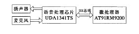
Figure 1 Hardware design sketch 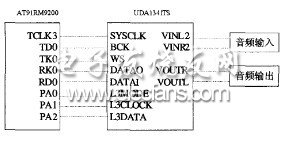
Figure 2 Hardware circuit connection 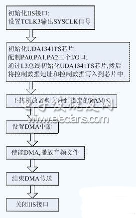
Figure 3 IIS interface function test software design flow chart