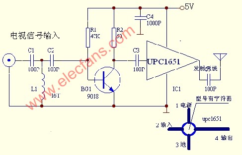
Circuit diagram of low-power broadband TV transmission â—† The working principle of the low-power wide-band TV transmitter circuit is that the RF signal is sent to a high-pass filter composed of C1, L1, and C2 through a 75-ohm RF cable, and the frequency lower than 45MHZ is filtered, and then composed of a transistor 9018 After the preamplifier is amplified, it is sent to upc1651 by Capacitor C3 for power amplification, and its output signal is transmitted through a whip antenna of about 60 cm. 7805 constitutes voltage stabilization and power supply instructions to provide 5V power supply for upc1615. â—† Debug this transponder circuit can also be placed in a small iron box or a waste VHF high-frequency head. As long as the mechanical and electronic components are removed, it becomes a shielded box. Due to the transponder circuit Simple, few components, you can solder the component directly on the circuit board, and ensure the connection is correct, welding is correct! The working current of the whole machine is about 25MA. The working current of 9018 is about 5MA, which can be adjusted by R1. VCR, VCD The RF output cable of household appliances should be a 75-ohm coaxial cable with a length as short as possible. It is fully shielded [including the joint part], which can reduce the interference of the RF antenna. As long as the quality of the components is guaranteed, the transmitter can work normally. â—† Material selection upc1651 is a high-gain high-frequency amplification integrated circuit, 9018 is a low-noise ultra-high frequency triode, C1, L1, C2 constitute a high-pass filter with a cut-off frequency of 47MHZ. The capacitors are selected high-frequency ceramic dielectric capacitors. The resistors are made of ordinary carbon Membrane resistance. IC2 and other components provide 5V power supply and power indication. The L1 is made on a cylinder with a diameter of 3mm and is tightly wound with 0.2mm enameled wire for 16 turns. The antenna uses a 60cm whip antenna. In the high frequency band, when designing the printed board and manufacturing, the configuration of the components and the length of the leads must meet the requirements of high-frequency design. As far as possible, the welding line is ultra-short, which is close to the circuit board. This circuit uses miniaturized components and can be installed in the 47x33x16mm plastic box provided by this site. The power supply uses a 9V DC stabilized power supply. It does not occupy much space in the room or living room. Friends who have multiple TVs in their home and cannot communicate with the signal line can refer to the production. Our company is specialized in supplying Welding Torch . Quick self-lighting,Brazes/Solders,Swirl Flame,variable flame control,Tip swivels 360 degree. Generates more heat than other hand torches. Faster brazing times and less gas consumption. Long life life. 4 interlocking safety button,reliable to use,comfortable handling. Designed for Propane or MAPP.CGA600 connections .Adjustable pressure .Use with MAPP or PROPANE TANKSTypical ApplicationsUsed for Copper/ Brass Tubes Welding/Brazing.Used for Copper/ Brass Fittings or Welding/Brazing.Valve Body made of Brass.For use with 14.1-16 OZ Containers.HVAC After Market Welding Torch Welding Torch,Welding Machine,Mapp Gas Torch,Gas Welding Torch ZHEJIANG ICE LOONG ENVIRONMENTAL SCI-TECH CO.,LTD. , https://www.china-refrigerantgas.com