Application of directional valve in commutation and locking circuit DirecTIon Valve Used in Reversal and Locking Loop 5.4.1 Reversal Circuit (1) Simple commutation circuit For a single reversing circuit, just use a standard common reversing valve between the pump and the actuator. (2) Complex commutation circuit When frequent and continuous automatic reciprocating motion is required and there are many additional requirements for the commutation process, a complex commutation loop is required. For a host with high reversing requirements (such as various types of grinding machines), if the manual reversing valve is used, automatic reciprocating motion cannot be achieved. The motorized directional valve is used to push the lever (connected to the directional valve stem) on the stroke of the worktable to realize automatic reversal. However, when the worktable moves slowly, when the directional valve moves to the middle position, The worktable will stop moving due to the loss of power (called "commutation dead point"), and automatic commutation cannot be achieved; when the worktable moves at high speed, the reversing spool will move too quickly and cause reversal shock. If an electromagnetic reversing valve is used, the travel stop switch pushes the travel switch to send a reversing signal, so that the action of the solenoid valve pushes the reversal, which can avoid "dead spots". There are defects such as low commutation frequency, low life and easy failure. In order to solve the above two contradictions, a specially designed mechanical hydraulic directional valve is used to push the motorized pilot valve with a travel stop, which controls an adjustable hydraulic directional valve to realize the commutation of the worktable, which can avoid the "commutation". "Dead spot", and can eliminate the commutation impact. This commutation circuit can be divided into two types: time-controlled braking and stroke-controlled braking according to different commutation requirements. ①TIme Control Brake Reversal Circuit l-throttle valve; 2-pilot valve; 3-directional valve; 4-overflow valve As shown in Figure 5.25, the main oil circuit in this circuit is only controlled by the directional valve 3. In the reversing process, for example, when the pilot valve 2 is in the left end position, the pressure oil in the control oil path passes through the check valve to the right end of the reversing valve 3, and the oil at the left end of the reversing valve flows back through the throttle valve J1 The oil tank, the directional spool moves to the left, the brake cone on the spool gradually closes the oil return channel, the piston speed gradually slows down, and the channel is closed after the spool of the directional valve 3 moves by a distance of l, Stop the piston. The half cone angle of the brake cone on the spool of the reversing valve is generally 1.5 ° to 3.5 °, and it can be larger where the reversing requirements are not high. The length of the brake cone l can be determined according to the test, generally l = 3 ~ 12mm. When the size of the openings of the throttle valves J1 and J2 is set, the time required for the spool of the directional valve to move by the distance l (that is, the time experienced by the piston brake) is determined to be unchanged (not considering the effect of oil viscosity change) ). Therefore, this braking method is called time-controlled braking. The main advantage of this commutation circuit is: its braking time can be adjusted according to the speed of the host component movement speed, the size of the inertia through the opening amount of the throttle valve J1 and J2, in order to control the commutation shock and improve work efficiency; in addition The H-type of the reversing valve is used to reduce the impact and improve the stability of reversing. The main disadvantage is that the amount of punching out in the commutation process is affected by the speed of the moving parts and other factors, and the commutation accuracy is not high. This kind of commutation circuit is mainly used in the occasions where the moving speed of the working parts is high, and the commutation is required to be stable without impact, but the accuracy of the commutation is not high, such as the surface grinder and the hydraulic system of the insertion, drawing and planing machine. ②Travel Control Brake Reversal Circuit As shown in Figure 5.26, the main oil circuit in this circuit is controlled by the pilot valve 2 in addition to the directional valve 3. When the pilot valve 2 moves to the left during the commutation process, the right brake cone of the spool of the pilot valve gradually closes the oil return passage of the right chamber of the hydraulic cylinder, which gradually slows down the piston speed and pre-brakes the piston. When the oil return passage is closed very small (the axial opening remains about 0.2-0.5mm), and the piston speed becomes very slow. The control oil path of the directional valve 3 starts to switch, and the directional valve core moves to the left. Cut off the main oil passage, stop the piston, and then start it in the opposite direction. Here, regardless of the original speed of the moving part, the pilot valve always has to move a fixed stroke l, pre-brake the working part, and then change it by the directional valve. So this braking method is called the stroke control braking type. The brake cone of the pilot valve generally takes the length l = 5 ~ 12mm. Reasonable selection of the brake taper can make the brake smooth (and there is no need to use a longer brake cone on the directional valve. The length of the brake cone is only 2mm, half The cone angle is also larger. l-throttle valve; 2-pilot valve; 3-directional valve; 4-overflow valve The stroke control brake type commutation circuit has higher commutation accuracy and smaller stroke volume; but because the brake stroke of the pilot valve is constant, the length of the braking time and the magnitude of the commutation impact will be affected by the speed of the moving parts The impact of speed. Therefore, this kind of commutation circuit should be used in the occasions where the moving speed of the working parts of the main machine is not high, but the accuracy of commutation is high, such as in the hydraulic system of the grinder. 5.4.2 Locking Circuit The locking circuit can stop the piston of the hydraulic cylinder at any position and prevent it from pulsating after stopping. The simplest way to lock the actuator is to use the M-type or O-type neutral position of the three-position directional valve to close the two chambers of the hydraulic cylinder, so that the actuator can be locked at any position of its stroke. However, due to the inevitable leakage of the spool valve directional valve, this locking method is not reliable enough, and is only suitable for circuits with short locking time and low requirements. The most commonly used method is to use a hydraulically controlled check valve, the locking circuit of which is shown in Figure 5.27. Because the hydraulic control check valve has good sealing performance, even under the action of external force, it can make the actuator lock for a long time. In order to ensure the locking when the three-position directional valve is in the neutral position, the directional valve should adopt H-type or Y-type functions. This circuit is often used in the outrigger oil circuit of truck cranes, and also in the locking circuit of hydraulic supports of mining and mining machinery. Enershare's commitment to future-ready energy solutions for smart home innovations, Enershare's Energy Storage Systems create a flexible energy maintenance system for homeowners who want to take more control of their home energy use, it is intended to be used for Home Battery energy storage and stores electricity for solar self-consumption, load shifting, backup power, and off-the-grid use. you can use it anytime you want-at night or during an outage. large battery system,large electric power system,large electricity station,high capacity for residential/commercial application,emergency reserve of household electric power,off-grid battery system Shenzhen Enershare Technology Co.,Ltd , https://www.enersharepower.com
In the hydraulic system, the starting, stopping or changing the direction of motion of the working mechanism is achieved by controlling the on and off of the oil flow into the actuator and changing the flow direction. The loop that realizes these functions is called the direction control loop. Directional valves are mainly used for On-off Control, Reversal Control, Locking, Sustaining, etc. 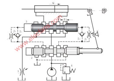
Figure 5.25 Time-controlled braking commutation circuit 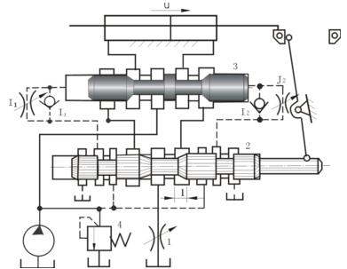
Figure 5.26 Stroke control braking commutation circuit 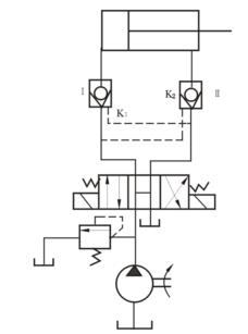
Figure 5.27 Locking circuit