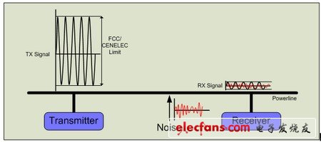
Power line communication (PLC) is a communication technology that uses power lines as a communication medium. Data is transmitted on the same power line as the power supply, so that the existing power infrastructure of the house or car can be used to transmit data without adding new wires. Powerline communication technology is experiencing rapid growth and has found ways to enter multiple applications and markets, including smart grids, lighting control, solar panel monitoring, energy metering, home video distribution, electric vehicles, and more. Energy conservation is being promoted globally, which has promoted the need for energy-generating and energy-consuming equipment to communicate with each other. Powerline communication provides a unique method without the need to build new facilities, enabling intelligent energy management technologies to quickly spread all over the world. Unlike wireless solutions, power line communication is not limited by line of sight and transmission range. Power line communication is also a low-cost and easy-to-install technology for many applications. Today, system designers can buy power line communication devices from more than ten semiconductor suppliers. Many of these devices are optimized for specific applications and markets. With such a wide range of choices now, developers need to understand the factors that affect the performance and reliability of power line communication systems and overcome the usual design challenges. Any communication system includes four main components: 1. transmitter 2. Receiver 3. Communication medium 4. The signal itself As mentioned earlier, the communication medium for power line communication is power line. Figure 1 shows a general power Block diagram of the line communication system. The transmitter modulates the signal and sends it to the power line. The receiver at the other end demodulates the signal and receives the data. When reaching the receiver, the signal is attenuated by the impedance of the power line. When the signal passes through power, any noise in the medium will also destroy the signal. Figure 1: A block diagram of a typical power line communication system. The power line impedance attenuates the transmitted signal. Line noise can significantly affect the signal. Briefly introduce the basics, let us introduce the factors that affect the performance and reliability of the power line communication system one by one. These factors include: 1) Send signal strength 2) Power line noise 3) Power network impedance 4) Network protocol 5) Receiver sensitivity I will make some suggestions one by one for these factors. Finally, several stages and system costs will be discussed. Transmit (Tx) signal strength A stronger Tx signal means that more signal power passes through the power line. Stronger signals are less susceptible to power line noise and can be transmitted farther. The strength of the Tx signal will also affect the power consumption of power line communication nodes, because the more signal energy is input to the power line, the more energy the node consumes. More ideally, developers will increase the signal strength of the transmitter until they reach the best performance and power consumption of the power line. However, Tx signal strength is tightly controlled by some organizations, such as FCC in North America and CENELEC in Europe. FCC and CENELEC also regulate sound waves, which can be transmitted to the power line by the main Tx signal. What these regulations do is to prevent signals in different frequency bands from interfering with each other. When choosing a power line communication device, check whether the Tx signal meets the strength requirements of the target market. It should also comply with FCC and CENELEC standards. Ideally, the Tx gain should be configurable so that you can debug the Tx signal strength according to other systems. In addition, confirm how much energy the PLC node consumes, so as to achieve the best transmitted signal strength required by FCC and CENELEC. Of course, the less energy consumption, the better. Power line noise Once the transmitted signal is injected into the power line, its integrity depends on the noise level on the line-the stronger the noise, the greater the damage to the noise signal. Power line noise can come from multiple sources. Power line noise can be simply divided into two types: pulse type and continuous type. Impulse noise is unpredictable and appears in a pulse sequence, as shown in Figure 2. For example, this type of noise can come from a mixer switch in the kitchen. It is difficult to design a system that can tolerate unpredictable, huge impulse noise without reducing the data rate. A more common situation is that this type of noise will completely cover any packet on the line. Figure 2: Power line impulse noise Continuous noise, on the other hand, is easier to predict than impulsive noise (see Figure 3). Continuous noise usually depends on the quality of the power line installation in the community, city, or country. Because power infrastructure was originally designed to efficiently transmit power rather than data, power line installations rarely pay attention to line noise levels. Depending on where the system works, the power line noise may be large or small. Figure 3: Continuous noise on the power line In order to be able to communicate robustly on the power line, the signal-to-noise ratio (SNR) needs to be kept at a certain threshold. If there is continuous noise with high amplitude in the frequency range of the PLC system, it is best to isolate the noise. It can be removed from the PLC receiver or by adding an intercepting inductance at the power supply end of the noise-generating device to weaken the noise frequency below Receiver signal-to-noise ratio. Evolis Cleaning Kit,Evolis Primacy Cleaning Kit,Evolis Cleaning Card,Evolis High Trust Cleaning Kit Miraclean Technology Co., Ltd. , https://www.mrccleanroom.com