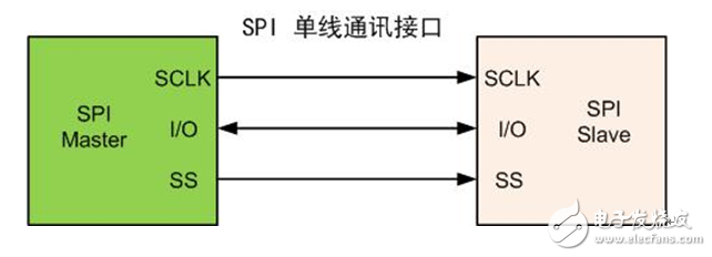
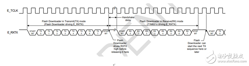
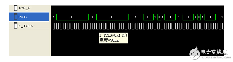
1, the standard SPI communication protocol SPI is the abbreviation of Serial Peripheral Interface, which is a high-speed, full-duplex, synchronous communication protocol. SPI Usually four wires are required, which are MOSI (data output), MISO (data input), SCLK (clock), SS (chip select). (1) MOSI - main device data output, slave device data input; (2) MISO – master device data input, slave device data output; (3) SCLK – clock signal, generated by the master device; (4) SS – slave device enable signal, with master device control; Figure 1 SPI standard communication interface The advantage of the SPI communication interface is that it can transfer data quickly, can reach several megabytes to several tens of megabytes, and has no system overhead. However, the shortcomings of the SPI bus are also obvious, mainly because there is no specified flow control, and there is no response mechanism to confirm whether data is received. 2. Single line SPI interface There is also an alternative SPI communication interface. This SPI interface is modified on the standard SPI interface, changing from the original two data lines to one data line. In this way, the communication method has also become a half-duplex communication party, which is more simple on the wiring. Figure 2 SPI single-wire communication interface 3. Let the programmer be the SPI single-wire communication interface of the slave In the programming world, chips that have encountered special programming interfaces have become commonplace. Because sometimes, in order to design a better programming method, the chip will adopt some rare and wonderful communication methods. When supporting the programming of some chips of MAXIM, the chip adopts the SPI communication of the single data line of the chip as the host, and its communication characteristics are: (1) TCLK is generated by the chip from start to finish, and the programmer receives the clock; (2) The clock frequency is higher, reaching 10MHz; (3) The communication method is that the chip returns one byte every time it receives a byte. The data communication is shown in the figure below (Note: the picture is from the programming manual). Since the master-slave interchange problem does not occur during the communication process, the enable pin SS can also be ignored. Figure 3 programmer's single data line SPI communication as slave For this series of chips, because the communication clock frequency is high, the data should be sampled. The programmer's sampling clock is at least 20MHz, and the hardware needs to be well compatible, and the programmer must immediately switch to the receiving state after sending the data. It is difficult for a general programmer to meet such demanding requirements. The processing scheme used here is supported by the P800-ISP using a super-fast processor. The following figure is a communication waveform that intercepts the process from the logic analyzer to the programming process. It is obvious that the clock width of the clock is 50 ns (the corresponding clock frequency is 10 MHz). Figure 4 Single-line SPI communication waveform The summary of the single-line SPI programming interface is as follows: Advantages: less wiring (the actual used line only needs two), fast communication, simple data; Disadvantages: However, when the high-frequency communication is demanding on the slave, it needs to be compatible with the switching of the high-frequency sampling and transmission and reception status (for example, switching to the receiving state immediately after transmitting the data).
PCB
Connectors: Backplane, Wire-to-Board, Board-to-Board Connectors
These types of connector systems are
mounted or processed to a printed circuit board (PCB). There are a variety of PCB connectors and accessories best designed for specific uses. To name some, they include: Din41612 Connector ,Board To Board Connectors,Battery Holders Clips Contacts, Future Bus Connectors , PLCC Connectors .
Din41612 Connector
Board To Board Connectors
Battery Holders Clips Contacts
Future Bus Connectors
PLCC Connectors
1.ANTENK manufactures a wide range of application specific board stacking PCB connectors which were designed and built to specific customer requirements. Our experienced staff has developed custom products in a variety of contact styles, pitches and stacking heights. Our designs range from new concepts to duplicating existing market products identically or with improvements. Many desigsn are produced using automated manufacturing processes to increase reliability and provide significant cost savings.
2.Our products are widely used in electronic equipments,such as monitors ,electronic instruments,computer motherboards,program-controlled switchboards,LED,digital cameras,MP4 players,a variety of removable storage disks,cordless telephones,walkie-talkies,mobile phones,digital home appliances and electronic toys,high-speed train,aviation,communication station,Military and so on
What is a Pcb Connector ?
Other names for PCB Connectors
PCB Connectors can be known as PCB Interconnect product. Specific terms are also used for the two sides of the connection. Male PCB Connectors are often referred to as Pin Headers, as they are simply rows of pins. Female PCB Connectors can be called Sockets, Receptacles, or even (somewhat confusingly) Header Receptacles.
Din41612 Connector,Board To Board Connectors,Battery Holders Clips Contacts,Future Bus Connectors,PLCC Connectors ShenZhen Antenk Electronics Co,Ltd , https://www.antenk.com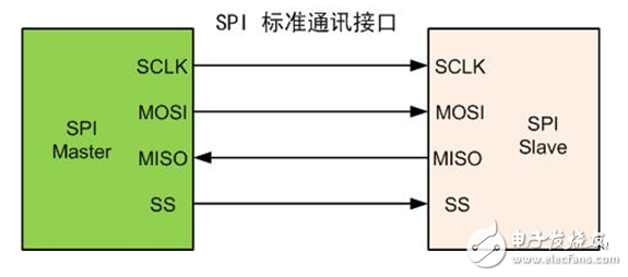


Printed Circuit Board Connectors are connection systems mounted on PCBs. Typically PCB Connectors are used to transfer signals or power from one PCB to another, or to or from the PCB from another source in the equipment build. They provide an easy method of Design for Manufacture, as the PCBs are not hard-wired to each other and can be assembled later in a production process.
PCB Connector orientations
The term PCB Connector refers to a basic multipin connection system, typically in a rectangular layout. A mating pair of PCB Connectors will either be for board-to-board or cable-to-board (wire-to-board). The board-to-board layouts can give a range of PCB connection orientations, all based on 90 degree increments:
Parallel or mezzanine – both connectors are vertical orientation;
90 Degree, Right Angle, Motherboard to Daughterboard – one connector is vertical, one horizontal;
180 Degree, Coplanar, Edge-to-Edge – both connectors are horizontal orientation.