Rotary encoders are photoelectric devices that convert angular displacement into digital signals, typically in the form of high-speed pulse outputs. They are widely used in industries such as machine tools, elevators, servo motors, textile machines, packaging systems, printing equipment, and lifting machinery. These devices play a crucial role in motion control, position tracking, and speed measurement. There are two main types of rotary encoders: incremental and absolute. Incremental encoders generate periodic electrical signals that correspond to the movement, and the number of pulses indicates the distance or angle moved. Absolute encoders, on the other hand, assign a unique digital code to each position, allowing for direct position reading without needing to return to a reference point. The key difference between the two is how they determine position. Incremental encoders rely on counting pulses from a zero reference point, while absolute encoders provide an immediate and accurate position reading based on their internal code. This means that even after power loss, an absolute encoder retains its position information, whereas an incremental encoder must re-find its zero point before operation can resume. Figure A (Structural principle): Photosensitive elements are typically made up of phototubes, which detect light patterns generated by the encoder's code disk. Setting the zero position is a critical step when using incremental encoders. There are several methods to achieve this: Best practices for setting zero include choosing a non-zero position with some margin for error and using a midpoint offset method. This ensures stable operation and avoids position jumps during rotation. Encoders can also be classified based on how the code wheel is engraved: Connection example between encoder and PLC: Note: Power supply can vary between DC 5V and DC 24V depending on the application. Common issues with encoders include: In addition to position feedback, encoders can also provide speed signals to frequency converters, enabling precise motor control. When an encoder fails, the inverter may not function properly, resulting in slow operation or protection mechanisms being triggered. The display might show “PG disconnection,†indicating a problem with the encoder signal connection. Proper configuration of the PG interface is essential to ensure compatibility between the encoder and the inverter. In summary: The light from the LED is refracted by the lens into parallel beams, which pass through the grating and code disk. As the code disk rotates, the light pattern changes, and the receiver converts these optical signals into electrical pulses. These pulses represent the physical motion in terms of displacement, velocity, and acceleration. Dual Axis Solar Tracker System Dual Axis Solar Tracker System,Sun Power Single Axis Solar Tracker,Dual Axis Solar Sun Tracker pv tracker,Pv Solar Tracking System Hebei Jinbiao Construction Materials Tech Corp., Ltd. , https://www.pvcarportsystem.com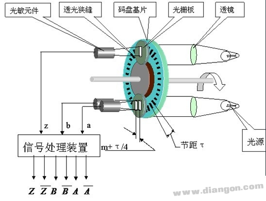
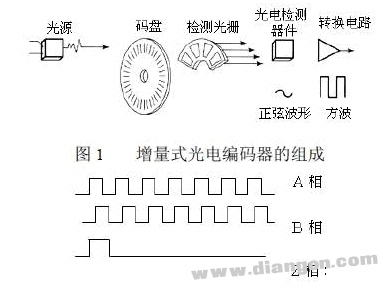
Figure B (With inverter wiring)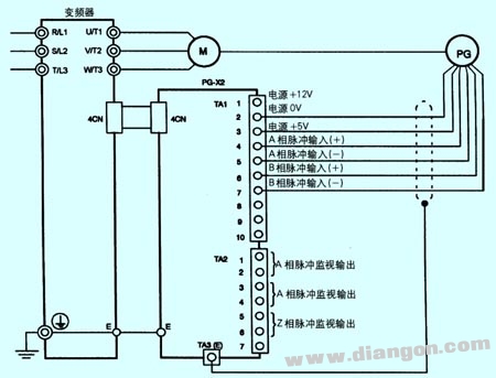
Figure C (Incremental type)
Figure D (Absolute type)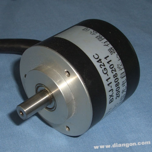
In most industrial applications, incremental encoders are preferred because they can directly interface with PLCs through high-speed counters. However, absolute encoders are often used in applications where maintaining position data during power cycles is essential.
Encoder
PLC
A
X0
B
X1
Z
X2
+24V
+24V
COM
-24V
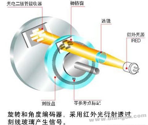
1: Light source (LED) 2: Lens 3: Indicating grating 4: Disk 5: Receiver (ASIC)