Rotary encoders are photoelectric devices that convert angular displacement directly into digital signals, typically in the form of high-speed pulse outputs. They are widely used in industries such as machine tools, elevators, servo motors, textile machinery, packaging, printing, and lifting equipment. There are two main types of rotary encoders: incremental and absolute. An incremental encoder produces a periodic electrical signal that is converted into counting pulses. The number of pulses indicates the magnitude of the displacement. On the other hand, an absolute encoder assigns a unique digital code to each position, making its readings independent of the measurement process. This means that even after power loss, the absolute encoder retains its position information, while an incremental encoder must re-find the zero point after restart. The difference between the two lies in how they determine position. Incremental encoders rely on counting pulses from a reference point (zero), whereas absolute encoders read a unique code at each position, ensuring accuracy without needing a reset. Here’s a breakdown: Below are some schematic diagrams illustrating the structure and operation of different types of encoders: In many applications, especially with PLCs, incremental encoders are commonly used. Their pulse output can be directly connected to a PLC's high-speed counter to measure displacement accurately. However, for accurate positioning, the zero point must be set correctly. There are several methods to set the zero point: Encoders can also be classified based on their code wheel engraving method: Connection diagram between encoder and PLC: tangram_guid="TANGRAM__38" Note: Power supply can be DC 5V or DC 24V. Common issues include: Rotary encoders can also provide speed feedback to frequency converters, helping regulate motor performance. If the encoder fails, the inverter may display “PG disconnection†and become unstable. In summary, rotary encoders are essential in precision control systems. They convert mechanical motion into digital signals, allowing for accurate measurement of position, speed, and acceleration. Their design typically involves a light source, lens, grating, and receiver to process optical signals into electrical pulses. The LED emits light that is focused through a lens onto the grating and code disk. As the disk rotates, the pattern of light changes, and the receiver translates these optical variations into electrical signals, which represent the physical motion in terms of displacement, velocity, and acceleration. Oblique Single Axis Solar Tracker System Oblique Single Axis Solar Tracker System,Oblique Single Axis Solar Tracker System Customized,oblique single axis solar tracker system device Hebei Jinbiao Construction Materials Tech Corp., Ltd. , https://www.pvcarportsystem.com
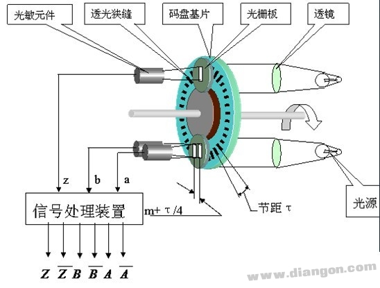
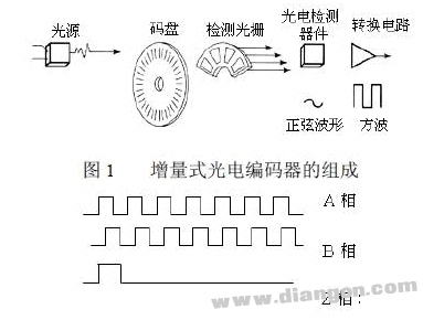
Figure B (with inverter wiring)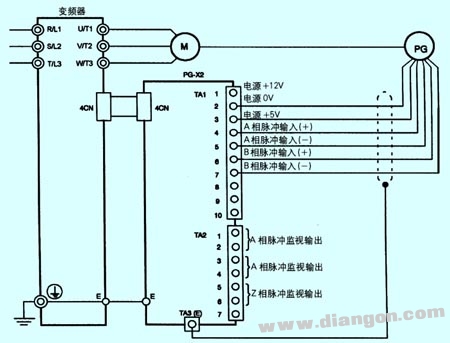
C picture (incremental type)
D picture (absolute type)
Encoder-----------PLC
A-----------------X0
B-----------------X1
Z------------------X2
+24V------------+24V
COM------------ -24V-----------COM
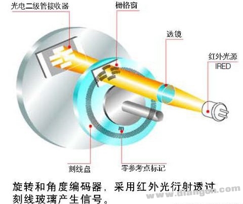
1: Light source (LED) 2: Lens 3: Indicating grating 4: Disk 5: Receiver (ASIC)
Rotary encoder zero position - Solutions - Huaqiang Electronic Network
Each battery array has an independent axis of rotation ontrolled by a solar tracking device, ensuring that the photovoltaic modules are parallel to the sunlight in the vertical plane. The inclined single axis bracket can increase power generation by 25% -35%.