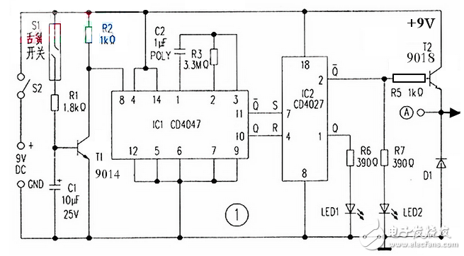
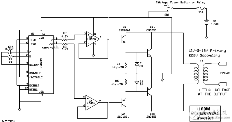
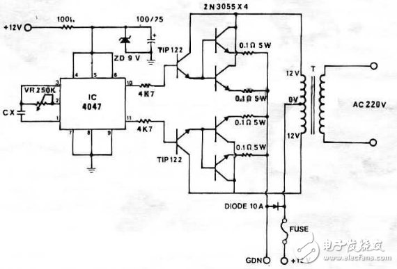
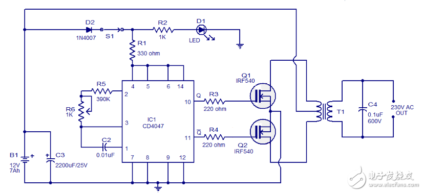
1. Signal Control Circuit Using CD4047 and CD4027 The signal control circuit is built using two integrated circuits: the CD4047 and the CD4027. The CD4047 (IC1) operates in a monostable multivibrator mode triggered by a positive edge. It is used to set and reset the CD4027 (IC2). The pulse width at the output of IC1 depends on the resistor R3 and capacitor C2 connected between pins 1 and 2. Under normal conditions, when the gate is closed, the reed switch S1 is activated, which turns on transistor T1. This keeps the one-shot circuit IC1 in standby mode, with output pin 10 at a low level. When the gate opens, the reed switch S1 disconnects, causing T1 to stop conducting. A transition from low to high voltage at the collector triggers IC1, resulting in a 10-second positive pulse at output pin 10. At the same time, the complementary output (pin 11) goes low. These signals are used to set or reset IC2. IC2 is a dual JK master-slave flip-flop that changes state based on the rising edge of the clock signal. When its reset pin (pin 4) receives a high pulse, the Q output goes high. Conversely, when the set pin (pin 7) receives a high pulse, the Q output goes low, and the complementary output (pin 2) goes high. This activates LED 2 and turns on transistor T2, which powers the alarm circuit. 2. AC Inverter This inverter converts a 12V DC input from a car battery into a 220V AC 50Hz or 60Hz square wave signal. Key components include the IC4040 and LM358, along with transistors 2SC1061 and 2N3055. The transformer has a secondary winding of 12V and a primary of 220V. The inverter can deliver more than 100W of power with a current of 3A. Notes: 3. 100W Inverter Using Transistor This circuit uses an IC 4047 combined with 2N3055 transistors to build a 100W inverter. Other configurations use NE555 and 2N3055 for 300W inverters, or NE555 and CA3130 for higher power systems. A 500W inverter can be built using 2N3055 for 12V to 220V conversion. 4. Inverter Circuit Using CD4047 and IRF540 MOSFET This is a simple 100W inverter circuit using the CD4047 and IRF540 MOSFETs. It's cost-effective and easy to assemble on a veroboard. The CD4047 is configured as an astable multivibrator, generating two 180-degree phase-shifted pulses at pins 10 and 11. These pulses drive the gates of the MOSFETs Q1 and Q2. Resistors R3 and R4 prevent overloading the ICs. When pin 10 is high, current flows through the upper half of the transformer, producing the positive half of the AC waveform. When pin 11 is high, current flows through the lower half, creating the negative half of the AC cycle. Circuit Diagram: Precautions: 5. 12V to 220V Inverter Circuit Based on CD4047 12V to 220V Inverter Circuit Diagram To calculate the transformer rating, use the formula: Power P = Voltage V × Current I. For example, if you want to output 220W at 220V, the output current would be 1A. At 12V input, the required current would be approximately 18.3A (since 12V × 18.3A ≈ 220W). Note that this calculation doesn't account for transformer efficiency losses. 2.0mm Pitch 2.0mm Pitch HuiZhou Antenk Electronics Co., LTD , https://www.atkconn.com