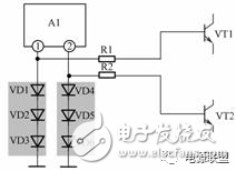
Once a diode is forward-biased, its forward resistance changes slightly depending on the current passing through it. The higher the forward current, the lower the forward resistance; conversely, the smaller the current, the higher the resistance. This characteristic between forward current and resistance allows for the construction of automatic control circuits. For example, Figure 3.1 shows an automatic level control (ALC) circuit made up of diodes, commonly used in recording systems of magnetic devices like tape decks. Figure 3.1: Diode-Based Automatic Control Circuit 3.1 Preparation for Circuit Analysis The unidirectional conduction property of a diode simply means that it has low resistance when forward-biased and high resistance when reverse-biased. However, this does not provide detailed information about the specific behavior once the diode is conducting. After being turned on, the forward resistance of the diode decreases as the forward current increases. Therefore, the larger the forward current, the smaller the resistance, which is important for designing certain control circuits. Understanding the function of a circuit is crucial for analyzing its working principle. In the context of a recorder or tape deck, the ALC circuit is designed to regulate the amplitude of the recording signal. Here are some key requirements: (1) When the recorded signal amplitude is small, no control is applied. (2) When the signal amplitude becomes large enough, the ALC circuit begins to control the signal by reducing its amplitude. (3) The greater the input signal, the more it is attenuated by the ALC circuit. Such analysis requires a comprehensive understanding of circuit behavior, which can be developed through continuous learning and practice. 3.2 Working Principle of the Circuit The analysis of this circuit involves several key points: (1) Without the VD1 branch, all signals from the first-stage amplifier would go directly to the second stage. However, with the VD1 branch, part of the signal may flow through C1 and the forward-biased VD1 to ground, causing a shunt effect that reduces the signal strength. (2) The capacitor C1 in the VD1 branch is typically an electrolytic capacitor, meaning it has a large capacitance and can pass AC signals. This makes VD1 a critical component for shunting the signal. (3) The more the signal is shunted through VD1, the less it reaches the second stage, and vice versa. (4) VD1 can either be on or off. When it is off, there is no shunting effect. When it is on, it creates a shunt path for the signal. (5) A resistor R1 provides a control voltage to the positive terminal of VD1. This voltage determines whether the diode is on or off. Once VD1 is conducting, its forward resistance depends on the current flowing through it—higher current leads to lower resistance. 3.3 General Approach to Analyzing Control Circuits Control circuits are often analyzed based on different conditions, such as varying levels of the control signal. In this case, the control of VD1 by the DC voltage Ui can be divided into the following scenarios: (1) When there is no recording signal, the control voltage Ui is zero, so VD1 remains off. If VD1 is faulty, it can cause issues such as distortion or lack of signal control. When VD1 is open, the circuit cannot control the signal. Large signals may cause distortion, while small signals may appear normal. If VD1 is shorted, the signal will be heavily attenuated due to the diode shunting it to ground. 4. Diode Limiting Circuit and Fault Handling One of the basic functions of a diode is to switch between on and off states, making it ideal for building limiting circuits. A limiter circuit restricts the amplitude of a signal at a particular point in the circuit. When the signal exceeds a certain threshold, it is limited, but otherwise, it passes through without interference. Figure 4.1 shows a diode limiting circuit using multiple diodes and transistors. This type of circuit is commonly used to protect components from overvoltage. Figure 4.1: Diode Limiting Circuit 4.1 Circuit Analysis Ideas To understand how the diodes VD1–VD6 work in the circuit, consider the following: (1) The configuration of VD1–VD3 and VD4–VD6 is similar, and both sets serve the same purpose. Therefore, analyzing one set is sufficient. (2) The output pin of the integrated circuit (A1) is connected to the base of transistor VT1 via resistor R1. This indicates that the signal is passed to the transistor, and the presence of a DC voltage suggests that the diodes are used for limiting rather than normal signal transmission. (3) The DC voltage from the pin is not high enough to turn on the diodes under normal conditions. Otherwise, they would shunt the AC signal and reduce its amplitude, which is not desired in this application. (4) If the AC signal amplitude is too large, it could damage the transistor VT1 during the positive half-cycle. The diodes help prevent this by limiting the signal amplitude. 4.2 Operation of the Diode Limiting Circuit Analyze the circuit in two cases: when the signal amplitude is small and when it is large enough to trigger the limiting action. Figure 4.2 shows the waveform of the signal on pin 1 of the integrated circuit. When the AC signal is small, the diodes remain off, allowing the full signal to pass through. When the signal is large enough, the diodes conduct, clipping the excess part of the signal to protect the transistor. High-Speed 3D Filament Extrusion Line,Precision 3D Filament Extrusion Line,Customizable 3D Filament Extrusion Line,Advanced 3D Filament Extrusion Line Technology Zhejiang IET Intelligent Equipment Manufacturing Co.,Ltd , https://www.ietmachinery.com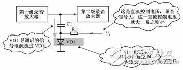
Simulation design analysis ideas and hardware knowledge preparation
3. Diode Control Circuit and Fault Handling