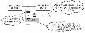
Simulation design analysis ideas and hardware knowledge preparation

3. Diode Control Circuit and Fault Handling After a diode is turned on, its forward resistance changes slightly depending on the current passing through it. The larger the forward current, the smaller the forward resistance, and vice versa. This characteristic between forward current and forward resistance can be used to design automatic control circuits. As shown in Figure 3.1, an automatic level control (ALC) circuit using a diode is commonly found in recording systems of magnetic devices like tape decks.

Figure 3.1: Diode-Based Automatic Control Circuit

3.1 Preparation for Circuit Analysis

The unidirectional conduction property of a diode indicates that its forward resistance is low and reverse resistance is high. However, this does not explain the specific behavior after the diode is turned on. Once conducting, the forward resistance of a diode decreases with increasing forward current. So, the more current flows through it, the lower the resistance becomes. Understanding these characteristics is essential when analyzing circuits involving diodes. In recording devices such as tape recorders, the ALC circuit controls the amplitude of the input signal during recording. The following conditions help in understanding how the diode-based ALC circuit works: (1) When the signal amplitude is small, no control is applied. (2) When the signal amplitude is large enough, the ALC circuit starts to limit the signal, reducing its amplitude. (3) The greater the signal amplitude, the more it is attenuated by the ALC circuit. To analyze such circuits, a comprehensive understanding of diode behavior and circuit functions is necessary. Continuous learning and practice are key to mastering this knowledge.

3.2 Working Principle of the Circuit

The main points of the circuit analysis include: (1) Without the VD1 branch, all signals from the first-stage amplifier reach the second stage. With VD1, some of the signal may flow through C1 and VD1 to ground, creating a shunt effect that reduces the signal. (2) C1 is a large-capacity capacitor, typically an electrolytic one, which allows AC signals to pass through. Therefore, VD1 plays a crucial role in shunting the signal. (3) If more of the signal is shunted through VD1, less reaches the second stage amplifier. (4) VD1 can be either on or off. When off, there is no shunting; when on, the signal is attenuated. (5) R1 provides a control voltage to VD1, determining whether it turns on or off. The relationship between the forward current and resistance of the diode is critical in analyzing the circuit.

3.3 General Analysis Method for Control Circuits

Control circuits are usually analyzed under different conditions, such as low, medium, and high input levels. For the diode VD1 in this circuit, the control voltage Ui determines its state. (1) When no signal is present, the DC control voltage Ui is zero, so VD1 is off. If VD1 is open, the circuit loses control, leading to distortion at high signal levels. If it is shorted, the signal gets shunted to ground, resulting in reduced output.

4. Diode Limiting Circuit and Fault Handling

A diode can be used to create a limiting circuit, which restricts the amplitude of a signal. When the signal exceeds a certain threshold, the limiter prevents further increase. Otherwise, it has no effect. Figure 4.1 shows a typical diode limiter circuit, including components like integrated circuits, transistors, resistors, and diodes.

Figure 4.1: Diode Limiting Circuit

4.1 Circuit Analysis Ideas

Analyzing the role of VD1 and VD2 involves several key points: (1) The two sets of diodes (VD1–VD3 and VD4–VD6) have similar structures and serve the same purpose. (2) The signal from pin 1 of the IC is connected to the base of transistor VT1 through resistor R1. This suggests that pin 1 outputs a combined AC and DC signal. (3) The DC voltage from pin 1 is not high enough to turn on the diodes, so they remain off under normal conditions. (4) Large AC signals can cause damage to the transistor if not limited. The diodes act as protection against excessive signal amplitudes. (5) Based on these observations, the diodes VD1–VD3 function as a limiting circuit, protecting the transistor from overvoltage.

4.2 Operation of the Diode Limiting Circuit

There are two main cases in a limiter circuit: (1) When the signal amplitude is small, the limiter does not activate, and the signal passes through unaffected. (2) When the signal is large enough, the diodes turn on, limiting the signal’s amplitude. By examining the waveform of the signal at pin 1 of the IC, we can better understand the operation of the limiter. When the AC signal plus DC voltage is below the diode's threshold, the diodes remain off. When it exceeds the threshold, the excess signal is clipped, preventing damage to the transistor.

PVC PE Pipe Production Line

High Capacity Pvc Pe Pipe Production Line,Precision Pvc Pe Pipe Production Line,Affordable Pvc Pe Pipe Production Line,Customizable Pvc Pe Pipe Production Line

Zhejiang IET Intelligent Equipment Manufacturing Co.,Ltd , https://www.ietmachinery.com