In modern households, it's common to find various electronic devices such as televisions, VCD players, video recorders, gaming consoles, and even video cameras or DVD players. These devices often transmit RF signals that can be captured and retransmitted using a TV signal transmitter. If the signal is received by a television set located about 30 meters away within the same room, you can avoid the hassle of running cables, making the setup more convenient. This allows users to watch content in different rooms without any complicated wiring.
The device functions like a small home TV station, acting as a signal repeater. It’s an easy-to-build solution with a simple circuit design, low cost, and straightforward construction. This makes it ideal for DIY enthusiasts who want to expand their TV signal coverage without investing in expensive equipment.
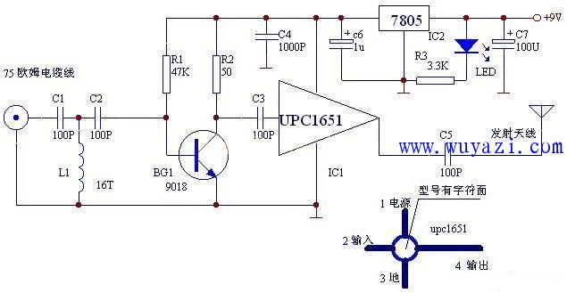
The circuit diagram illustrates the working principle: the RF signal from the source is sent through a 75-ohm coaxial cable to a high-pass filter composed of C1, L1, and C2, which filters out frequencies below 45MHz. The remaining signal is then amplified by a preamplifier made up of a transistor like the 9018. After that, the signal is passed through a coupling capacitor (C3) to the UPC1651 chip for power amplification. Finally, the amplified signal is transmitted via a 60cm whip antenna.
To ensure stable operation, the circuit includes a voltage regulator, such as the 7805, which provides a steady 5V supply to the UPC1651. This setup ensures reliable performance and minimal interference, making it a practical option for extending your TV signal range at home.
Single Phase High Frequency Tower UPS Single Phase High Frequency Tower UPS,Tower Single Phase Online UPS Shenzhen Unitronic Power System Co., Ltd , https://www.unitronicpower.com