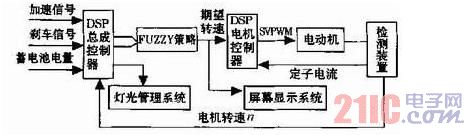
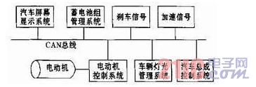
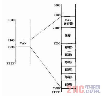
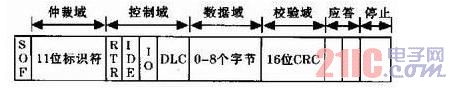
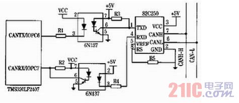
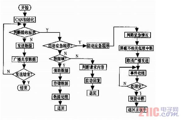
Virtual Instrument (VI) is a new achievement that is increasingly developed in the process of intensive penetration of computer hardware, software and bus technology into other related technologies. . Since the specialized functions of the instrument and the panel controls are formed by software, such new instruments are called "virtual instruments" internationally. It uses the data processing and graphics processing functions of the microcomputer to softwareize the specialized functions and panel controls of the traditional physical instruments, and the interface between the detected data is also realized by computer software. From the virtual instrument display panel (such as virtual display, digital display and indicator light and oscilloscope, which corresponds to various physical instruments in function), you can understand the state of the instrument and read the test results for analysis. This article refers to the address: http:// 1 Vehicle load cell overview According to the characteristics of the virtual instrument, the vehicle load detecting device of the capacitive load cell is used as the elastic body of the load cell in the vehicle buffer damping mechanism, and the static or dynamic detection can be performed anytime and anywhere. Under the action of the load, the buffer damping mechanism (plate spring) of the automobile is deformed, and the distance between the two plates of the capacitive sensor installed at a specific position changes, the capacitance value changes, and the output voltage of the sensor also changes. Based on the parameter analysis of the static performance of the virtual instrument, the law of the voltage change between the two pole plates of the capacitive sensing 货物 when the vehicle changes at rest is analyzed, which is used as a reference for testing the dynamic performance. It is convenient and intuitive to analyze the voltage value corresponding to a specific load and use the virtual instrument program subVI to perform error analysis and curve fitting. The installation of the capacitive load cell is shown in Figure 1. The upper plate part of the capacitor is mounted on the lower part of the frame, centered on the left and right; the lower plate part of the capacitor is mounted above the middle of the axle, and is aligned with the upper plate of the capacitor. A set of capacitive sensors is mounted above each axle of the vehicle. The relationship between the elements of the vehicle weighing system is as follows: Under the action of the load, the shock absorbing mechanism (steel spring) of the automobile is deformed, and the distance d between the two plates of the capacitive sensor changes, and the capacitance value of the sensor also changes. The relationship between the output voltage value of the sensor circuit and the load value of the axle is pre-calibrated, and the load quality of the axle can be obtained according to the voltage value of each axle sensor circuit. By adding the load masses of the respective axles, the overall vehicle load quality can be obtained. The static analysis test for detecting vehicle load based on the virtual instrument-based capacitance method was performed on the Panther SM1010. The vehicle is a two-axis leaf spring construction with a rated load of 500 kg. During the static experiment, the vehicle was kept in a horizontal state, and the two wheels were vertically pressed on the SCS-2蛩 electronic digital platform scale. The vehicle is loaded or unloaded with a 100 kg weight as a standard unit load. The test is divided into two strokes (each stroke includes both positive and negative directions), which are loaded or unloaded in the following order: Forward 1 - in the free state of the vehicle (no hysteresis), gradually load from no-load until the sensor output reaches full scale; The software programming adopts modular design, which mainly includes curve fitting module, straight line fitting and error analysis module. The least square linearity, hysteresis error and repeatability error in the error analysis module are in the form of subVIs, which provides great convenience for the analysis and programming of dynamic parameters. The error processing module mainly analyzes and processes the data repeatability error, maximum standard deviation and hysteresis error in the process of analyzing data. These data are used as a basis for subsequent data processing and capacitive load cell compensation system programming, such as repetitive error programming as shown in Figure 4. In order to grasp the influence of acceleration on the load detection of the capacitive method vehicle, according to the corresponding relationship between the pre-calibrated load mass and the output voltage of the capacitive sensor, the load quality of the front and rear axles and the whole vehicle under a certain acceleration (aH) is obtained. The results are shown in Table 1. The results of the above analysis system show that the capacitive vehicle weighing device has good repeatability when it is static, but it also has certain nonlinear error and large hysteresis, which directly affects the load detection result. The main cause of nonlinear errors is the relationship between the relative change in capacitance and the nonlinearity between the plates. There are two main reasons for the hysteresis (including the reverse stroke not returning to zero): 1) the real material has hysteresis to some extent; 2) the height and length of the leaf spring vary with the load when the vehicle load is different. Changes, friction between the spring pieces, friction between the two ends of the spring piece and the frame. The use of leaf springs with highly elastic materials, improved mechanical design, and reduced friction can reduce the effects of hysteresis. The use of software for nonlinear compensation and hysteresis compensation is very obvious. 3 Conclusion In order to solve the numerous control and data exchange problems in modern vehicles, Bosch developed a CAN (Controller Area Network) fieldbus communication structure. The CAN bus hardware connection is simple, with good reliability, real-time performance and price/performance ratio. CAN bus can meet the needs of modern automation communication, and has become the most important one in the field of industrial data bus communication. Its main features are: 1CAN bus is a multi-master bus, each node can actively send information to other nodes on the network at any time, regardless of master-slave, flexible communication; 2CAN bus uses a unique non-destructive bus arbitration technology, The node with higher priority preferentially transmits data, which can meet the real-time requirement; 3CAN bus has the function of point-to-point, point-to-multipoint and global broadcast data transmission; 4 CAN bus has a maximum of 8 valid bytes per frame, and has CRC and Other verification measures, data error rate is extremely low, in case of a serious error in a node, it can be automatically disconnected from the bus, other operations on the bus are not affected; 5CAN bus has only two wires, when the system is expanded, the new node can be directly It can be hung on the bus, so there are few wires, the system is easy to expand, and the modification is flexible. The 6CAN bus has a fast transmission speed. When the transmission distance is less than 40m, the maximum transmission rate can reach 1Mb/s. It is precisely because the CAN bus has the advantages that these other communication methods cannot match, making it an ideal bus for electric vehicle control systems. 1 The demand for communication networks in electric vehicles Due to the limited capacity of energy storage equipment, electric vehicles are very strict in energy management during operation. Efficiency is an important indicator to measure the performance of electric vehicle systems. The national 863 “fifteen†electric vehicle major special requirements motor system rated efficiency is 85%. The rated efficiency of the controller is 95%. The dynamic information of the electronic control system of the electric vehicle must be real-time. Each subsystem needs to share the public data of the vehicle in real time, such as motor speed, wheel shift, accelerator pedal position and brake pedal position. However, the control cycles of different control units are different, the data conversion speed and the priority of each control command are different. Therefore, a data exchange network with priority competition mode is needed, and it has a very high communication rate. In addition, as a kind of load For people's transportation, electric vehicles must have good comfort. The vehicle communication system must have strong fault tolerance and fast processing capability. At present, the development of electric vehicles has been highly valued by countries. Electric vehicles have become the mainstream of future automobile development. There are many electrical components in electric vehicles, and there are many data that need to be transmitted and shared in real time. How to improve the real-time, reliability and emergency processing capability of electric vehicle communication becomes the difficulty of electric vehicle communication. We use TMS320LF2407 DS as the electric vehicle communication system. The main processor uses DSP's good fast processing capability to improve the data processing speed, thereby improving the real-time communication; using the CAN bus module embedded in the DSP as the CAN controller, reducing the complexity of the hardware circuit, thereby improving the reliability of communication. Sexuality; the emergency response capability of electric vehicles is improved by software design emergency time shielding secondary factors. 2 control plan The electric vehicle assembly control uses advanced fuzzy control, and the controller used is also the TMS320LF2407 type DSP. The collected brake signal, the acceleration signal and the feedback speed signal are blurred to obtain the desired speed signal, and the obtained speed value is transmitted to the motor control mechanism through the CAN bus to control the motor to satisfy the driver. Driving intentions. Simultaneous management of the lighting system and screen display system. The on-screen display system displays the operating status of the electric vehicle in real time. The specific control scheme is shown in Figure 1. Figure 1 Block diagram of electric vehicle control system 3 electric vehicle CAN bus communication scheme Electric vehicle control requires good communication coordination and operational reliability. A good communication system is the key to the reliable operation of electric vehicles. The CAN bus structure is a serial communication network that effectively supports distributed control or real-time control. Figure 2 is a schematic diagram of a typical electric car CAN bus structure, including the main motor controller, battery management system, electric vehicle screen display system and other equipment in the power part of the vehicle. These subsystems communicate with each other via CAN. Command transmission. Each node device can independently complete the operation of its own system without leaving the CAN bus, thus meeting the needs of vehicle operation safety. At the same time, the CAN bus will not collapse due to the detachment of a certain device. Figure 2 Electric vehicle CAN bus structure diagram 4 CAN bus module The CAN bus module is a 16-bit peripheral of the DSP and is a complete CAN controller. In addition to the basic functions of the CAN bus, there are some unique functions, such as: the object has six mailboxes, and the data length is 0~ 8 bytes, two of which receive mailboxes (0, 1), two send mailboxes (4, 5), two can be configured to receive or send mailboxes (3, 4); automatic reply remote request function; programmable CAN bus wake-up function; self-test mode function, etc. Access to the CAN bus is divided into control/status register access and mailbox RAM access. The memory space allocation diagram of the CAN bus control module is shown in Figure 3. Figure 3 CAN bus memory space allocation There are two kinds of information frames sent by the CAN controller, one is to send data frames, the other is to send remote frames. The sending mailbox has mailbox 4 and mailbox 5 and the mailbox 2 and mailbox configured to send mode. When sending data frames After the data is written to the data area of ​​the sending mailbox, if the corresponding sending request bit is enabled, the data frame is sent to the CAN bus. The data area of ​​the data frame can be set to 1-8 bytes by software. The format of the data frame is shown in Figure 4. Figure 4 CAN bus data frame The receiving mailbox of the CAN bus controller has mailbox 0 and mailbox 1 and mailbox 2 and mailbox configured to receive mode. When receiving the information, the CAN controller first needs to receive the identifier of the receiving information and the corresponding receiving mailbox identifier. In comparison, only the information with the same identifier can be received. The receive register of the CAN bus controller allows the receiving mailbox to ignore more bits to receive the information. However, if the receive mask enable bit (AME) is 0, then local The Receive Mask Register will be disabled. Only Mailbox 2 and Mailbox 3 configured as Send Mode can receive Auto Answer Remote Frames. When the mailbox receives a remote frame, the receiving node will automatically send a data frame as a response. 5 interface circuit design Since the DSP itself has a CAN bus module, there is no need for a dedicated CAN controller. The DSP itself does not have a CAN transceiver. It requires an external CAN transceiver 82C250 and an optical isolator 6N137. If the distance is short, optical isolation is not required. The hardware connection diagram of DSP and opto-isolator and CAN transceiver is shown in Figure 5. Figure 5 DSP and CAN bus hardware connection diagram 6 Software implementation of CAN communication for electric vehicle assembly controller The electric vehicle assembly controller is the heart of the electric vehicle. It needs frequent receiving and transmitting data to control and detect the electric vehicle in real time. The sending information is in the inquiry mode, and the receiving information is interrupted. By setting different priorities of different events. To determine the order in which information is received and sent, and to increase emergency procedures to improve the controller's ability to handle emergencies, ensuring vehicle and personal safety. Emergency procedures are used when an emergency occurs, such as performing device damage, sudden braking and Sharp turn, etc., by temporarily shielding low priority events, such as battery power detection, LCD display system, etc., so that the controller has enough time to deal with emergencies to improve the controller's real-time control ability and emergency processing capability. The controller software flow chart is shown in Figure 6. Figure 6 controller software flow chart 7 Conclusion At present, fieldbus is rapidly developing in the field of automation. As a very influential field bus, CAN bus adopts many new technologies and designs, making CAN bus one of the most promising fieldbuses. With its high real-time, high reliability and high flexibility, CAN bus has been used more and more in industrial automation control. In this paper, the DSP controller is used as the microprocessor of CAN bus. It utilizes the strong data processing capability of DSP and the high transmission rate and high reliability of CAN bus to propose a solution to the complex communication system in electric vehicle. Experiment proves that this The system not only solves the real-time requirements of electric vehicle communication, but also improves reliability and stability. The virtual instrument-based vehicle weighing analysis system has the characteristics of convenient operation, friendly user interface and easy programming. Although the virtual instrument does not have a real instrument panel, it is far superior in function to traditional physical instruments. It has been proved that the vehicle weighing system based on virtual instrument is not only suitable for the static measurement analysis of vehicle load by capacitance method, but also suitable for dynamic measurement analysis with larger data volume. The innovation of this paper is to use the software panel of the virtual instrument to analyze the static measurement of the vehicle load by the capacitance method, which not only gets rid of the shortcomings of the list statistics, but also the results are convenient and fast.
Driver For SMT Machine contains Driver For JUKI SMT Machine, Driver For SAMSUNG SMT Machine, Driver For PANASONIC SMT Machine.
Siemens Controller Driver Boards
Siemens Controller Board Card
Controller Board
Siemens Control Pcb Board
Samsung Control Pcb Board
Samsung Controller Driver Boards
Smt Controller Board Card
Controller Driver Boards
Driver For SMT Machine Shenzhen Srisung Technology Co.,Limited , https://www.sr-smt.com
2 Test and data analysis
Reverse 1 - gradually unloaded to no load on the basis of positive 1;
Forward 2 - on the basis of reverse 1 (with hysteresis), gradually load from no load until the output reaches full scale again;
Reverse 2 - On the basis of the positive 2, gradually unload to no load.
According to the test data, the arithmetic mean of the two forward and reverse sensor outputs is obtained separately and the arithmetic mean of the total process is obtained. It is programmed by the virtual instrument programming software LabVIEW platform. The front panel of the block diagram is as follows.
From the table, it can be seen that during the braking process, the acceleration of the aH=4 m/s2 compared with the aH=0, the front axle load mass detected by the capacitive sensor is increased by 122.5%, and the rear axle is reduced by 60. .7%, the vehicle load mass increased by 14.9%; during acceleration, the acceleration aH=1.78 m/s2 compared with aH=0, the front axle load mass decreased by 55.7%, and the rear axle increased. It was 14.6% larger and the vehicle load quality was reduced by 14.4%. It can be seen that the acceleration has a great influence on the vehicle load detection. In order to ensure the accuracy of the detection result, software compensation must be used.
The relationship between the load mass and the acceleration plotted according to the data in Table 1 is shown in Fig. 5.