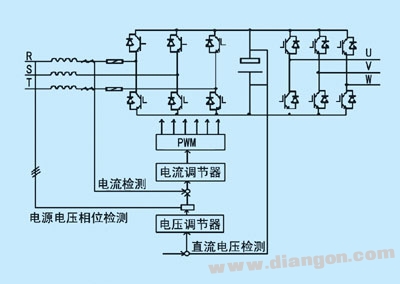
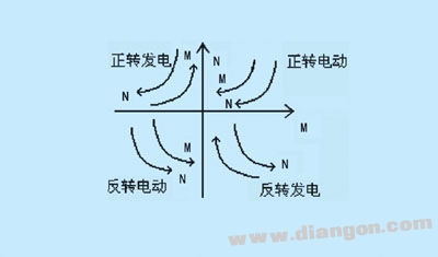
1 Introduction There are two common methods for handling regenerative energy in general-purpose inverters: (1) Energy dissipation through a brake resistor connected in parallel with the DC bus capacitor, known as energy consumption braking; and (2) Feedback of the energy back to the power grid, called feedback or regenerative braking. Another method is DC braking, used for precise parking or irregular stopping before motor startup. Many experts have discussed the design and application of inverter braking, particularly in recent years, with increasing focus on energy feedback braking. This article introduces a new braking method that combines the advantages of four-quadrant operation from feedback braking with high efficiency and the benefits of energy braking, such as no grid pollution and high reliability. 2 Energy Braking Figure 1: Schematic diagram of energy consumption braking 3 Feedback Braking Figure 2: Schematic diagram of feedback braking Figure 3: Four-quadrant motion map 4 New Braking Method (Capacitive Feedback Braking) 4.1 Main Circuit Principle During motor generation, the CPU monitors the AC input and DC link voltage Ud. When Ud exceeds the corresponding value, the CPU turns off VT3, allowing VT1 to pulse and charge the capacitor C. The reactor L and capacitor C work together to keep the capacitor within safe limits. If the voltage becomes too high, the safety circuit activates resistance braking to consume excess energy. When the motor is running, the CPU pulses VT3, causing the reactor L to generate a negative voltage, enabling energy feedback from the capacitor to the DC link. By monitoring the capacitor voltage and DC link voltage, the CPU controls the switching frequency and duty ratio of VT3 to prevent excessive Ud. 4.2 System Challenges (1) Reactor Selection Reactor selection is critical. In case of a fault, the motor may accelerate freely, generating high regenerative energy. The reactor must handle this current, so a large diameter is required. For the feedback loop, a ferrite core is preferred over silicon steel to reduce losses, though large ferrite cores may be expensive and hard to find. Therefore, it’s recommended to use separate reactors for charging and feedback loops. (2) Control Difficulties In the DC circuit, the voltage U4 is typically above 500 VDC, while the electrolytic capacitor C is rated for only 400 VDC. Controlling the charging process is more complex than energy braking. The voltage drop across the reactor must be carefully managed to ensure the capacitor remains within safe limits. During feedback, it's crucial to prevent the capacitor current from raising the DC link voltage too high, triggering overvoltage protection. 4.3 Main Applications and Examples
AC Input : 100V to 240V, DC Output: 12 volt at 2 amp rating . Please refer to the ASIN :B0746GCGQ8 if u need 10 units.
COMPACT DESIGN and LOW CONSUMPTION makes it ideal for taking around and using at home.
12v wall charger,12v switching adapter,(12V/2A) Switching Mode Power Adapter Wall Charger,12V 2A Power Supply Adapter,12 Volt 2 Amp Power Adapter,12V 3A Power Supply Adapter,12v 3a wall charger Shenzhen Waweis Technology Co., Ltd. , https://www.waweis.com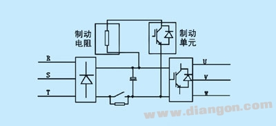

Manufactured with high quality material and built-in protection of over current, over voltage, short circuits .