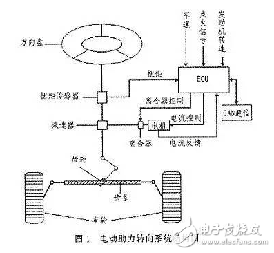
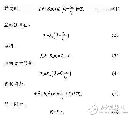
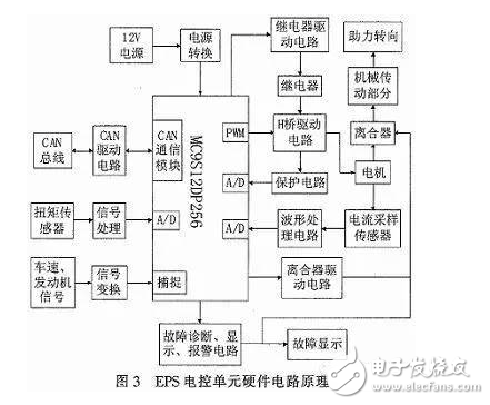
The steering system is an important part of the car, and its performance directly affects the stability and safety of the car. The early car steering system was a purely mechanical steering system with no power. The steering power was completely provided by the driver and the driving experience was poor. Since the 1930s, power steering systems have emerged. At present, there are three main forms of automotive power steering: Hydraulic Power Steering (HPS), Electric Hydraulic Power Steering (EHPS), and Electric Power Steering System (EPS). ). 1 Electric power steering system structure and working principle The structure of the electric power steering system is shown in Figure 1. It is mainly composed of a steering wheel, a torque sensor, an electronic control unit (ECU), a motor, an electromagnetic clutch, a speed reduction mechanism, and a rack and pinion steering gear. After the engine is ignited, the steering torque is measured by a torque sensor mounted on the steering shaft and sent to the ECU. The ECU calculates a boost characteristic curve and a control strategy based on the torque and the vehicle speed. The optimum current required by the motor, thus controlling the output torque and direction of rotation of the motor, and then applying it to the steering mechanism via the reduction mechanism, ultimately resulting in a steering force that is compatible with the driving conditions to assist the driver in steering. 2 control strategy 2.1 Establishment of EPS model According to Newton's law, a mathematical model of the steering system can be established. Where: Th is the steering wheel input torque, Js is the steering column, the disk assembly moment of inertia, Bs is the input shaft damping coefficient, Ks is the torque sensor stiffness coefficient, Tm motor output torque, Km is the stiffness coefficient of the assist motor and the speed reduction mechanism, Jm is the driving motor moment of inertia, Bm is the assist motor damping coefficient, M is the rack quality, Br is the rack and steering wheel viscous damping coefficient, Kr is the rack equivalent stiffness, G is the assist mechanism transmission ratio, and rp is the pinion radius , θs is the steering wheel angle, θm is the motor rotation angle, xr is the rack displacement, and Fr is the steering resistance. 2.2 Assist characteristic curve design The EPS assist characteristic is the relationship between the driver input torque and the motor assist torque (assisted current). During the driving process, the steering resistance decreases as the vehicle speed increases. In order to obtain the portability of the steering at low speed and the stability during high-speed driving, the motor assist torque decreases with the increase of the vehicle speed under the same driving conditions, and the motor does not assist when the vehicle speed exceeds a certain range. . There are three common power assist curves: linear, polygonal, and curved. The linear assist characteristic curve is simple in form and easy to adjust and implement in practice. Therefore, the linear boosting characteristics are used in the design of the controller. 2.3 Control algorithm The EPS system control is the control of the magnitude and direction of the motor current. The quality of its control algorithm directly affects the performance of the steering system. This paper adopts the PID control algorithm widely used in the field of industrial control. The PID control has high stability and reliability, strong real-time performance, simple control and debugging method, and is easy to implement. It is suitable for the control of automotive electric power steering system. Therefore, PID control is the main control strategy of the current EPS control system. 3 hardware design 3.1 Overall design The one-chip computer is the core of the controller, and its selection needs to consider various factors such as applicability, reliability, on-chip resources and price. Whether the selection of the MCU is appropriate or not directly affects the performance of the mechanism control system and the degree of design difficulty. This design uses Freescale's 16-bit high-precision MC9S12DP256 microcontroller. MC9S12DP256 has 5 CAN modules, 2 8-channel 10-bit A/D conversion modules, 8 PWM channels, bus speed 25 MHz, 5 V power supply, 112-pin LQFP package. This single-chip microcomputer has abundant internal resources and can greatly simplify the hardware circuit of the control system. Its high reliability is very suitable for EPS control. Pins not used in the design are routed to the board for subsequent development. The hardware design is shown in Figure 3. After the vehicle speed, engine and torque signal are processed, they are sent to the MC9S12DP256 MCU. After calculation by the MCU, the motor assist current value is obtained. After the drive circuit, the motor is applied to the assist motor to control the magnitude and direction of the motor output torque, and the motor current is sampled. And sent back to the microcontroller to form a closed loop control. Based on the power control, the motor protection circuit and fault diagnosis and prompt circuit are designed. Once the fault is detected, the clutch is immediately disconnected, the manual manual steering is used, and a fault signal is issued, thereby ensuring driving safety. Tomtom Battery,Tomtom Go Battery,Tomtom Start Battery,Tomtom GPS Battery Shenzhen Sunwind Energy Tech Co.,Ltd , https://www.sunwindbatterylm.com
Compared with the first two, EPS provides auxiliary torque from the motor, without oil system, which greatly reduces the complexity of the steering system of the car, and has obvious advantages in fuel efficiency, modularity, power-assisting effect and environmental friendliness. . According to the position of the EPS assist motor on the gear and the steering column assembly, the EPS system is divided into four types: steering column assist type, rack assist type, pinion assist type and double pinion assist type. Pinion and steering column assist are used in light vehicles, and double pinion assist is used in heavy vehicles. They are composed of three basic components: an electric control unit (ECU), a booster motor and a torque sensor mounted on the steering column. For the small car, the EPS controller is designed with the 16-bit single chip MC9S12DP256 of Freescale Company as the core.