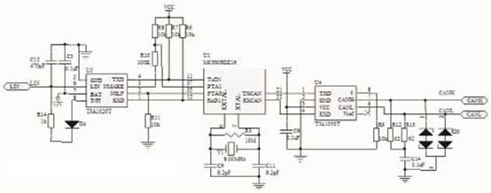
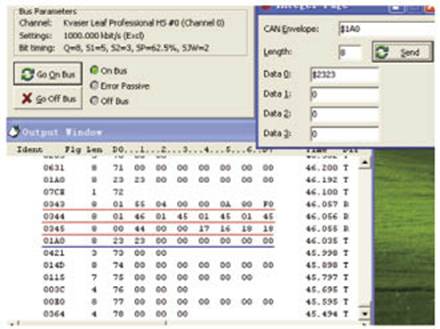
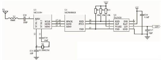
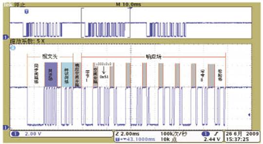
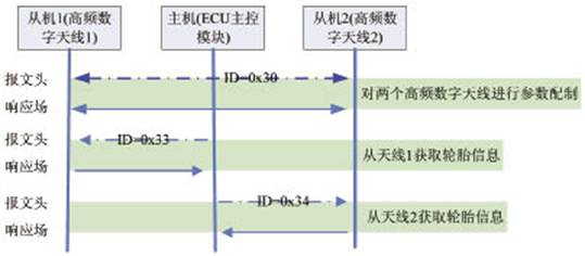
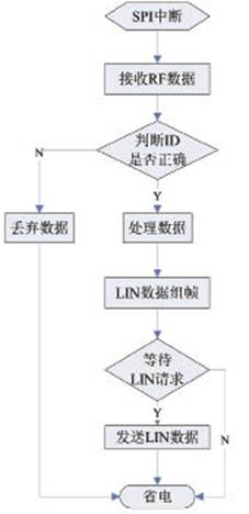
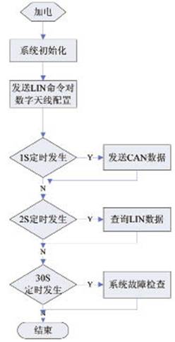
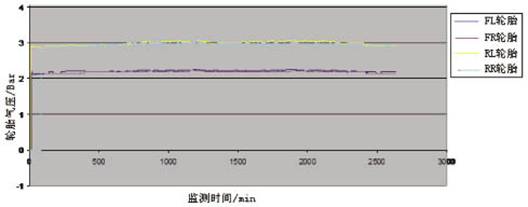
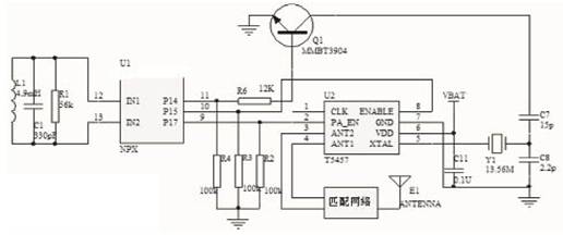
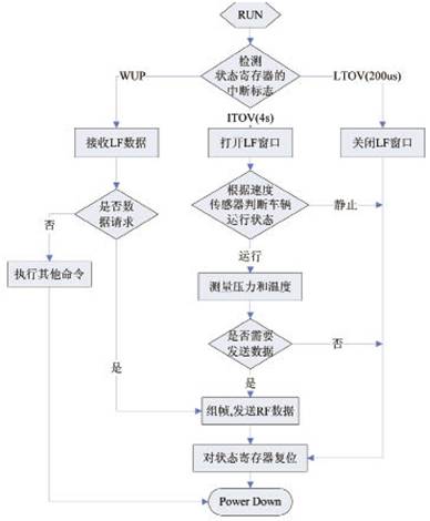
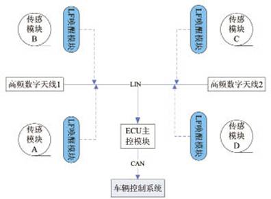
introduction This article refers to the address: http:// This paper introduces the design and application of TPMS in a foreign model, and introduces the design method of TPMS software and hardware in detail. The scheme integrates the design of CAN and LIN bus, meets the requirements of the whole vehicle wiring in the practical application of TPMS, and integrates with the whole vehicle bus, realizing the system and intelligence of TPMS. Project Requirements Analysis and TPMS System Design The design of TPMS is a system engineering. In addition to the design of the product itself, more attention needs to be paid to its application environment - the car itself, from the aspects of TPMS installation, wiring, function, performance, communication, interference, etc., to clarify the design of TPMS. Request to determine its technical solution. TPMS technical requirements analysis According to the specific environment of the vehicle, the special technical requirements for TPMS are analyzed as follows: a) RF signal transmission is a key technology in TPMS systems. When the emission signal in the tire is transmitted to the in-vehicle receiving system, the tire first causes the signal to attenuate. Secondly, the metal casing of the vehicle itself is equivalent to a shielding box, which causes the TPMS signal to be unstable. Especially for the high-end models targeted in this project, vehicles have a greater impact on RF signals. b) The tire pressure sensing module in the tire is the core content of the TPMS design. Due to the harsh application environment inside the tire, the design faces many difficulties. c) In the design of this project, the original car has the communication function of 1Mbps high-speed CAN, so the TPMS must be integrated with the CAN bus of the whole vehicle to realize the informationization and intelligent control of the system. TPMS application design The TPMS system consists of four tire pressure sensing modules, one ECU master module, two RF digital antenna modules, and CAN/LIN communication wires. The information processing and transmission process is shown in Figure 1. Figure 1 TPMS signal processing flow Design of Transmitter Module Based on NPX1 Sensor Chip Hardware circuit design of sensing module NPX is an integrated chip for high-precision sensors and low-power microcontrollers. It is a dedicated chip for TPMS. It has significant advantages such as complete functions, reliable performance and flexible application. Mainly to achieve tire pressure / temperature measurement, signal amplification, A / D conversion, data calculation and calibration, digital signal encoding output and other processes. The T5754 is a high-gain output RF chip that can be used to implement ASK/FSK modulated signals through different peripheral circuit designs. The external crystal oscillator Y1 provides the reference frequency for the chip. After 32 times of frequency, different frequencies can realize RF signals of 315MHz or 434MHz. Figure 2 is the schematic diagram of the tire pressure sensing module. The software sets P14 as the data stream output port. The high and low levels of the data stream continuously switch the conduction and closing of the collector transistor Q1 to reach the crystal capacitor Y1 load capacitance C7|| The capacitance value of C8 changes, thereby affecting the resonant frequency of the crystal oscillator and realizing the modulation function of FSK. In addition, C1, L1 and R1 in the circuit are connected in parallel to form a low-frequency interface, which is dedicated to receiving low-frequency signals of 125 kHz, which can realize active wake-up of tire pressure sensing, thereby performing function detection or two-way communication. Figure 2 Schematic diagram of the sensor module Sensing module firmware programming The firmware programming of the sensing module is mainly around power saving and reliability design. For the special application of TPMS, NPX has interrupt functions such as ITOV, LTOV, LF WUP, etc., so that the entire transmitting module can be in a sleep state for most of the time, and only when the interrupt occurs, it is in a short working state. Figure 3 is a firmware program flow chart. ITOV is a 4s timed interrupt main line workflow. When the vehicle is running, the tire pressure and temperature data can be sampled at intervals of 4s, and the tire information such as pressure and temperature can be wirelessly transmitted according to the system judgment; LTOV is a 200μs timed interruption. When the IOV and LTOV work together to open and close the low-frequency window, it can realize a low-frequency window of 200μs every 4s, waiting for the wake-up of the low-frequency signal, which can greatly reduce the power consumption of the whole sensor module; WUP wakes up the low-frequency signal. Interrupt, when the external device sends a low frequency signal of 125 kHz, the sensing module will be woken up, receive low frequency data, and send RF signal according to the low frequency command to realize the detection of the sensing module by the external device. In addition, the low frequency function is also applied to the two-way communication of the TPMS, and the active query of the sensing module by the TPMS receiving module can be realized. Figure 3 sensor module program flow Integrated CAN and LIN TPMS receiving system design The TPMS receiving system has strong system scalability. Especially for the design of the radio frequency digital antenna, the designer must make a reliable evaluation of the radio transmission environment of the specific vehicle, thereby determining the number of nodes of the radio frequency digital antenna on the LIN bus. In addition, according to the system design requirements, four low-frequency wake-up modules are extended on the LIN bus. For example, the blue part is the extended module on the LIN bus, which is installed near the tire, and is sent by the ECU main control module to the four low-frequency wake-up modules. The low frequency signal is sent by the low frequency wake-up module to activate the pressure sensing module in the tire to realize the two-way communication of the TPMS, and the active and real-time query of the tire information by the ECU main control module is achieved. Figure 4 LIN bus expansion diagram In the design of this project, according to customer needs and system radio environment, TPMS is designed as a one-way transmission system, and two RF digital antennas are installed before and after the chassis. Hardware circuit design of ECU main control module Figure 5 shows the principle design of the ECU main control module. MC9S08DZ16 is a high-performance 8-bit single-chip microcomputer introduced by Freescale. It adopts HCS08 core and has a maximum operating frequency of 40MHz. It has rich equipment resources such as CAN and LIN, and realizes data reception, processing, transmission and control of the whole system. The TJA1050 is a high-speed CAN transceiver with data rates up to 1Mbps; the TJA1020 is a LIN transceiver with a speed of up to 20kbps. Both chips are bus driver chips from Philips, which have strong EMC performance and transmission stability. In the design of this module, the circuit design of high-speed CAN is a key step, which is directly related to the compatibility and reliability of communication between TPMS and vehicle system. The design points are summarized as follows: a) PCB design: In high-speed CAN applications, PCB layout is critical to the routing of CAN components. On the one hand, it is necessary to ensure that the high-speed CAN transmission line is as short as possible, the wiring is compact, and the distributed capacitance is small to reduce the loop area. To enhance the anti-interference performance; on the other hand, to ensure the smoothness of high-speed signals, to avoid wiring bends and crossovers, it is easy to cause signal crosstalk and instability. Practice has proved that the PCB with reasonable wiring is not only stable but also has a long transmission distance. b) Load matching: In CAN network design, load matching between nodes and bus is an important indicator, especially for the design of high-speed CAN. As a node of CAN network in automotive systems, TPMS must fully consider the design requirements of system bus. c) Configuration of transmission rate: Each bit of CAN signal transmission consists of three parts, namely SYNC_SEG, T_SEG1, T_SEG2. We must balance the system requirements such as transmission rate and sampling point to make reasonable register configuration for CAN controller. In this system, as shown in Figure 5, the external crystal oscillator Y1 is selected to provide the CAN controller with a clock signal of fcanclk=8MHz, and SYNC_SEG=1, T_SEG1=4, T_SEG2=3, and bus prescaling Prescale Value="1" are respectively configured through registers. . CAN bus rate Sampling point Figure 5 Schematic diagram of ECU main control module d) CAN bus simulation and testing: After the software and hardware design of the CAN bus is completed, basic functions, performance simulation and testing are necessary processes. In this project, the Kvaser CAN bus diagnostic tool is used for simulation test, which can simulate the information exchange between the measured node and other CAN nodes on the network, and track the data transmission on the CAN bus in real time. In addition, the diagnostic tool can randomly send the interference data stream to the CAN bus to test the reliability of the data on the CAN bus. Figure 6 shows the data simulation test of the CAN tool. The data frames 0x343, 0x344, and 0x345 marked by the red line are the tire information and TPMS system status information sent by the ECU master module of the TPMS to the vehicle system; the data frame 0x1A0 marked by the blue line is the vehicle speed information sent by the simulated vehicle system to the TPMS; The data frame is an interference data frame randomly sent by the emulator on the bus. Figure 6 CAN bus simulation test chart Hardware circuit design of RF digital antenna The principle of the RF digital antenna is shown in Figure 7. It is mainly composed of a radio frequency receiving chip, a single chip microcomputer, and a LIN transceiver chip. The MC33594 is a high-sensitivity OOK/FSK receiver chip with automatic gain control. It is mainly responsible for receiving and demodulating RF signals, and transmits data to the MC9S08SG8 MCU through an SPI interface. The MCU processes the data to form a LIN. Packets, when there is a host requesting data on the LIN bus, the LIN packet will be sent to the LIN bus via TJA1020. Figure 7 schematic diagram of the RF digital antenna The message frame of the LIN bus consists of a message header and a response field. The waveform analysis diagram is shown in Figure 8. The header is sent by the host and includes a sync interval field, a sync field, and an identifier field, where the identifier field is the event command sent by the host to the slave. After receiving the command, the slave sends or receives 8-byte data and checksum according to the protocol, which constitutes the response field. Thereby, the host's one-to-one access and information transfer to each slave is completed. Figure 8 LIN data waveform analysis The LIN bus is a single-master multi-slave network structure. In the LIN bus design of this system, the configuration of the two RF digital antennas (slave) and the reading of the tire data are mainly realized by the ECU master module (host). Figure 9 shows the triggering of the information event on the LIN bus. Figure 9 LIN bus event trigger diagram Firmware programming for TPMS receiving system Figure 10 and Figure 11 are the firmware program flow charts of the RF digital antenna and the ECU master module. The RF digital antenna mainly receives RF data in SPI interrupt mode and sends LIN data frames in the manner of LIN request interrupt. The ECU main control module works in a timed inquiry mode: it automatically sends CAN data frames every 1s; it actively queries the data of the RF digital antenna every 2s; and actively detects the internal faults of the TPMS system every 30s. In addition, the ECU main control module can receive the data on the CAN bus in an interrupt mode, and realize the functions of registration, parameter setting and vehicle information sharing of the TPMS transmission module ID. Figure 10 RF digital antenna flow chart Figure 11 RF digital antenna flow chart Design verification The TPMS design is an automotive safety system with very high reliability requirements. A rigorous and scientific reliability verification plan must be developed from the perspective of failure analysis, including laboratory testing and field durability sports car testing. As shown in Figure 12, when the TPMS is installed on a foreign car for a durable sports car, the CAN analyzer is used to continuously collect and track the CAN data. The curves of the four different colors represent the air pressure of each tire in the running of the vehicle. Changes, as can be seen from the figure, the TPMS system is able to monitor tire pressure very accurately and reliably. Figure 12 TRMS system sports car test data tracking chart Conclusion Based on customer demand, this paper expounds a reliable TPMS technical solution, and introduces the design ideas and steps of TPMS from the typical application processes such as system analysis, solution construction, module design, system debugging and project verification. Although the system has complex layout and numerous modules, it completely solves the serious failure problem of TPMS wireless signal instability. According to the specific requirements of the vehicle environment, the system can be effectively reduced or expanded to meet the flexible design of different models. However, the design of TPMS is a complicated process after all. Especially in the application of different automotive environments, there are still many problems, and further research is needed to make TPMS more reliable and intelligent in automotive safety.
Headlight is Powerful light at the front of a vehicle. One car usually needs a pair or two pair of bulbs. It is depend on the original car design. Driver need power light to illuminate the road in front of them to keep them safe, so the halogen bulbs are usually been used as headlight. Halogen bulb can generate more light and has better working life hours. The supply voltage of halogen lamp is usually divided into ac 220V and dc 12V and 24V. The halogen lamp is made of tungsten, but it is enclosed in a smaller quartz glass shell. Normally, the halogen bulb will create ultraviolet when light, so we must use quartz coating to prevent head lamp been damaged by the ultraviolet generated by halogen bulb. To generate more light, the filament be heated to the very high temperature, so halogen bulb is hotter than a normal bulb.
Auto Headlight Bulbs Auto Headlight Bulbs,Powerful Auto Car LED,Yellow Automobile Head Lamp,LED Car Motorcycle Headlight Heshan Jianhao Lighting Industrial Co., Ltd. , https://www.sunclubtw.com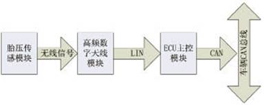
![]()