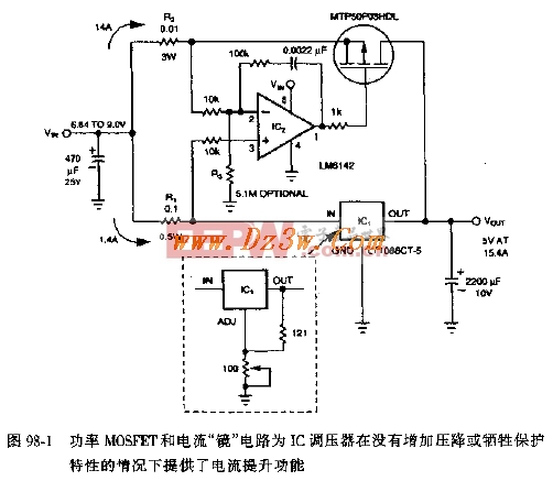
A MOSFET-based current booster circuit is shown in Figures 98-1 and 98-2. This design uses a current mirror and a power MOSFET to significantly increase the output current capability of an integrated circuit (IC) voltage regulator. The circuit retains all the built-in protection features of the IC, such as overcurrent, overvoltage, and thermal shutdown, while also providing additional safety for the MOSFET. Compared to a standard IC regulator that turns off when the output voltage exceeds its limit, this configuration offers a much smoother transition. When the load current reaches 10A, the output voltage only increases by about 0.1V. In these diagrams, R1 and R2 are current-sensing resistors. The current flowing through the IC regulator passes through R1, while the current through the MOSFET flows through R2. An operational amplifier (op-amp) controls the on-resistance of the MOSFET, ensuring that the voltage drop across R1 matches the voltage drop across R2. This allows the current through the MOSFET to be accurately mirrored at the IC's output, based on the ratio of R1 to R2. The op-amp can operate with its input common-mode voltage equal to its supply voltage, which means it can monitor the current even during power-up or under varying conditions. Additionally, the high gain of the op-amp allows for the use of small resistor values for R1 and R2, resulting in minimal voltage drops and improved efficiency.
AC DC power adapter 48v,48v power supply adapter,universal power adapter 48v,48v dc adapter ShenZhen Yinghuiyuan Electronics Co.,Ltd , https://www.yhypoweradapter.com