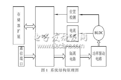
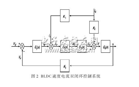
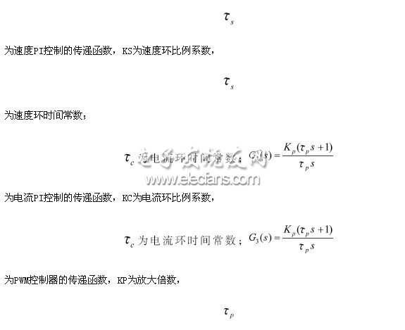
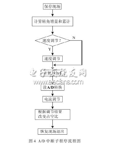
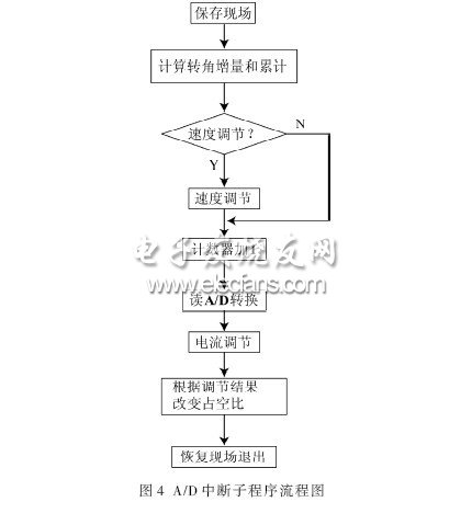
Research on Control System of Ice Coating Robot Based on DSP Ice and snow cover threaten the safe operation of power and communication networks [1-4]. The ice-covered robot is an automated device for removing ice from the transmission line. The robot needs to perform servo control on various motors such as a traveling motor, a joint motor, and a gripping and tightening motor. The types and quantities of motors are relatively large, so the robot control system is relatively complicated. This paper mainly studies the servo motor servo control of the ice-covered robot. The walking motor needs to drive the robot to walk on the line. When the line has a large ice coating, the deicing knife should be driven to complete the ice breaking work. During the operation of the robot, when the thickness of the ice layer is not continuously advanced, the robot automatically completes the retreat, accelerates the pre-shoot, and performs intermittent deicing. The servo motor servo control adopts the digital control brushless DC motor control system with the motor control special chip TMS320LF2407 as the core. The use of all-digital control can effectively avoid the interference of unstable factors in the analog control. Since the robot works in a strong electromagnetic environment, the fully digital control method can effectively avoid electromagnetic interference. Because the brushless DC motor has a series of advantages of AC motor with simple structure and reliable operation, and has the advantages of DC motor with high speed, high efficiency and high dynamic response, the system selects DC brushless motor as the robot axis drive [5] ]. 1 Control system overall structural design By analyzing the equation of motion of a DC motor, the motor acceleration is proportional to its torque, and the torque is proportional to its current. Therefore, to achieve high-precision and high-dynamic performance control of the motor, it is necessary to simultaneously measure the speed, current and position of the motor. Test and control. The system includes a position detection link and a current detection link to detect the speed and current of the motor. The hardware circuit of the system mainly includes DSP system, power drive circuit, isolation circuit, position detection circuit and current detection circuit. The structural principle of the system is shown in Figure 1. Digital Signal Processing (DSP) is an emerging discipline that covers many disciplines and is widely used in many fields. Since the 1960s, with the rapid development of computer and information technology, digital signal processing technology has emerged and developed rapidly. Digital signal processing is a method of processing real-world signals by performing transformations or extracting information using mathematical techniques, and these signals are represented by a sequence of numbers. In the past two decades, digital signal processing has been widely used in communications and other fields. Semiconductor manufacturers such as Texas Instruments and Freescale have strong capabilities in this field. 2 speed closed loop control A deviation is formed according to the input set value and the feedback amount, and a control amount of the PWM duty ratio is formed through a series of digital adjustments, thereby controlling the change of the rotational speed or speed of the servo motor. The speed closed-loop control is mainly responsible for the robot walking speed and speed change control during deicing. Figure 2 shows the speed and current double closed loop control system of brushless DC motor. When the BLDCM forms a speed closed-loop control, the rotation direction and rotation angle of the motor are detected by the photoelectric encoder and fed back to the DSP system. among them, Time constant of the first-order inertia link It is the back electromotive force constant of the motor under rated excitation; K1 and K2 are the proportional coefficients of current and speed feedback respectively; K3=R is the phase resistance of the motor; υg is the given speed of the motor; υs is the feedback speed of the motor; ig is the speed adjustment The output of the device, that is, the current reference value; if is the feedback current; IE is the current error signal; Uc is the PWM control signal; Ud is the motor DC terminal voltage; E is the motor opposite electromotive force amplitude; id is the motor phase current; n is The actual speed of the motor. 3 system hardware design 3.1 Phase current detection Because the power electronic main circuit uses two or two power-on methods. The current flows into only two phases of the three-phase winding at any time, so only one phase current detecting sensor is required to complete the phase current detection. Use a shunt resistor to sense each phase current. The resistor is located between the lower power bridge arm of the three-phase full-control power conversion circuit and the ground, and at the same time acts as an overcurrent protection. After the voltage drop signal on the resistor is amplified, it is sent to the A/D conversion channel on the TMS320F2407 chip, and the A/D conversion is performed to obtain a suitable current signal. After the A/D conversion is completed, the A/D conversion module will send an interrupt request signal to the CPU, waiting for the CPU to detect the current signal. Finally, according to the current error, the duty cycle of the PWM pulse is adjusted at the beginning of each PWM period [6]. 3.2 Rotor position and speed detection The TMS320LF2407A is used to realize the control and drive circuit of the three-phase brushless DC motor speed regulation. The Hall sensor with three positions spaced 120° is used, and the rotor position signal outputted by the Hall device is sent to the power conversion circuit, and then directly sent to the capture unit of the TMS320LF2407A for processing. Detecting the state of the three capture ports can obtain the combined state of the current three-way position signals, thereby obtaining the rotor position. Each capture captured by capture ports CAP1 to CAP3 triggers a capture interrupt, and each revolution of the rotor produces six capture interrupts. The motor speed is obtained by measuring the interval between two adjacent interruptions. 3.3 drive circuit design The motor control driver uses the IR2130 chip. The IR2130 chip controls the turn-on and turn-off sequence of six power transistors to control the forward and reverse rotation of the motor. This driver chip itself provides overvoltage protection for power devices. It contains a logic protection circuit. When the phase-to-stage pass-through logic occurs, the chip immediately outputs all low levels and turns off all MOSFETs. In addition, there is a sense resistor in the power loop protection device. When the current is too large, the detection signal is logically judged, PDPINT is set low, the DSP internal counter stops counting, all PWM outputs are low, and the drive circuit is turned off. Current protection [7]. 4 system software design The main program mainly completes DSP initialization, and the flow chart is shown in Figure 3. The A/D conversion interrupt subroutine completes the adjustment of speed and current, and the flow chart is shown in Figure 4. The experimental clock frequency is 20 MHz and the PWM frequency is 20 kHz. The A/D conversion is initiated by the timer 1 period match event, so that each PWM cycle is sampled once, and the current is controlled in the A/D conversion interrupt handler to control the PWM output. The capture interrupt program completes the counting of the position amount and calculates the speed reference amount. The program flow chart is shown in FIG. 5. The capture interrupt is triggered by a 60° angle of rotation of the rotor, and the commutation operation and speed calculation are performed [8]. In this paper, TI's TMS320LF2407A DSP is used to design a DC brushless motor control system for ice-skating robots during walking and de-icing. After analysis, the system is not only low cost, easy to implement, but also stable in performance and convenient to expand, which is of great significance to engineering practice and motor speed regulation. Metal junction boxed housing series, specail for North America,with UL/ETL certification,1-100W ,CE/ROHS/SAA/ETL/TUV/EMC,Input voltage can be both 110V and 220V,Wattage can be 1-80W, DALI/TRIAC/0-10V/PUSH dimmable and non dimmable, flicker free,noise free,load free, Perfect dimming curve, PF>0.95,constant current 350mA 700mA 900mA 1200mA,constant voltage 12V 24V 36V, parameters can be customization,OEM/ODM is supported,Same appearances but different sizes, forming a perfect product line,Use for led panel light,led strip light and other indoor led lights UL/ETL Junction Boxed Led Driver Metal Triac Dimmable LED Driver,Metal 0-10V Dimmable LED Driver,Metal DALI Dimmable LED Driver ,Metal PUSH Dimmable LED Driver HAURUI LIGHTING CO.,LTD , http://www.huaruileddriver.com
DSP (digital signal processor) is a unique microprocessor that uses digital signals to process large amounts of information. It works by receiving an analog signal and converting it to a digital signal of 0 or 1. The digital signal is modified, deleted, and enhanced, and the digital data is interpreted back into analog data or the actual environment format in other system chips. Not only is it programmable, but it can run tens of millions of complex instructions per second in real time, far surpassing general-purpose microprocessors, and is an increasingly important computer chip in the digital electronics world. Its powerful data processing capabilities and high operating speed are two of the most commendable features.