Specialed in developing and manufacturing in all kins of mobile phone chargers around 15 years with our own brand MLF, also with much OEM/ODM experience and including help our customer to do customized plastic housing mold . Our factory can output 300K pcs high quality USB 2.0 Mobile Phone Charger daily Mobile Phone Charger Mobile Phone Charger,Fast Phone Charger,Cell Phone Charger,Dual Usb Charger Meile Group Limited , https://www.hkmeile.com
Types of motors in industry
In the past 100 years, electrical products have mainly used induction motors. Even inverter-driven electrical appliances have also used induction motors. Some new electrical appliances are now adopting motors with higher efficiency, more compact size and lighter weight. These new motors can be divided into two major categories, namely brushless DC motors and switched reluctance motors.
Many common household appliances use brushless DC motors with variable frequency drives. This type of efficient general-purpose motor has a high torque density. As energy prices soared, the industry renewed interest in brushless DC motors. But for a long time, the cost and the overall complexity of the drive design have hindered the widespread adoption of this motor.
Switched reluctance motors are mostly used in appliances such as vacuum cleaners and hand-held power tools that do not pay attention to motor noise and torque fluctuations. Switched reluctance motors are characterized by high torque and high speed, but the price is very competitive.
Brushless DC motors and switched reluctance motors use a microcontroller or DSP to adjust the waveform, and then use a power switch (power MOSFET or IGBT) to amplify these adjusted waveforms.
Drive circuit
There are many different ways to design a variable frequency drive circuit. In a typical three-phase motor, the most popular low-frequency drive scheme is a trapezoidal wave drive circuit, as shown in Figure 1. Figure 2 shows the actual test waveform of the trapezoidal wave drive circuit. 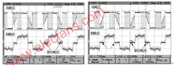
Figure 2: Trapezoidal wave control method and actual test waveform
There are two popular types of permanent magnet three-phase synchronous motors, namely sinusoidal permanent magnet synchronous motors and trapezoidal brushless DC motors. The sine permanent magnet synchronous motor is very similar to the trapezoidal brushless DC motor (electrical performance), and their differences are mainly reflected in the following two aspects: (1) the motor structure or the waveform of the back electromotive force (BEMF) is different, and one is the induced voltage Sine permanent magnet synchronous motor, the other is a trapezoidal brushless DC motor; (2) The waveform of the control voltage is different, one uses a three-phase sine (all three phases have current flowing at the same time), and one uses a rectangular six-step commutation.
Among the new drive devices, sinusoidal permanent magnet synchronous motors are becoming more and more popular. They have begun to replace brushed and brushless DC motors, general-purpose (AC asynchronous) motors and other motors (such as household inverter air conditioners and industrial sewing machines) in many applications. The reason is that it is more reliable (brushless), more efficient, less noise, and has a very high voltage utilization rate and low frequency torque in electrical control. Fig. 3 and Fig. 4 respectively give a system block diagram and experiment waveform of a position sensorless vector controller based on field-oriented control (FOC). 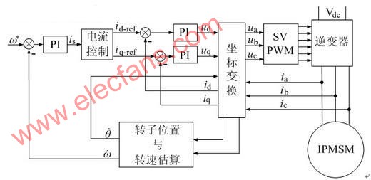
Figure 3: Block diagram of built-in permanent magnet synchronous motor (IPMSM) vector control system 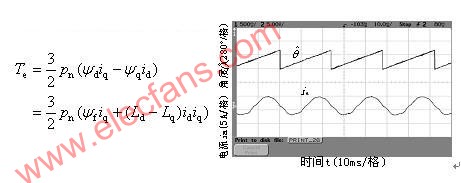
Figure 4: Electromagnetic torque equation and experimental waveforms of phase current and estimated angle
The Smart Power Module (SPM) is the power interface between the microcontroller or DSP and the motor, which can reduce the size of the motor and simplify the design. The advantage of this module over discrete solutions is that the parasitic inductance is smaller and the reliability is higher. This is because all power devices in the module use the same batch of chips and have consistent test performance. This intelligent power module can be directly interfaced with the low-voltage TTL or CMOS output of the microcontroller, and has a protection circuit. The module contains a thermistor to monitor the junction temperature, a logic protection circuit to prevent the upper and lower arms from passing through, dead time control, and a drive waveform shaping circuit to minimize EMI. In the module, each driver IC can be optimized so that it can complete the switching action of the power device with minimum EMI and drive loss. Three-phase drive modules will continue to be widely used in electrical products. Figure 5 shows a typical application circuit for motor control using SPM. 
Figure 5: Typical application circuit 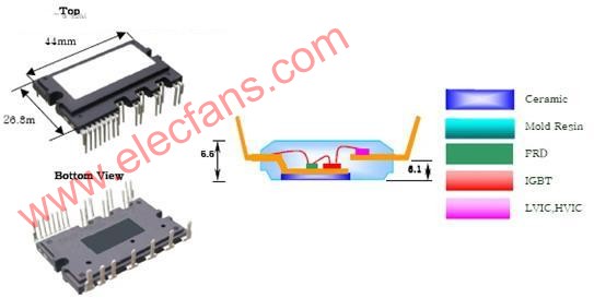
Figure 6: MoTIon-SPM appearance and internal structure diagram
The designed intelligent power module can achieve maximum design flexibility and can be used for different output voltages and power ranges.
High voltage (600V) bridge drive technology
(600V) High-voltage bridge drive technology can realize small and low-cost modules to promote the transformation of motor drive circuits. Modern high-voltage bridge gate drive circuits have been carefully designed to reduce the parasitic drain capacitance inherent in high-voltage IC chip processes. In this way, the drive circuit is very robust enough to withstand negative voltages above -9V. The positive and negative spikes on the power supply voltage will not cause latch-up and gate control failure of the drive circuit, which is a major change in the gate drive circuit in the past 10 years. The matched transmission delay is less than 50ns, which can make the switching frequency reach 100kHz or 150kHz. The added common-mode dV / dt noise cancellation circuit in the IC also helps to reduce the possibility of spurious conduction, which also helps to make the power circuit more robust, while also eliminating the need for additional filtering components, so More compact. Modern ICs (such as FAN7382 and FAN7384) have lower quiescent current and lower operating temperature, and therefore higher reliability. The reduction in system power board space and cost reflects a major advantage of modular technology, which eliminates the four power supplies common in the previous generation motor drive circuit and the photoelectric coupling circuit between the microcontroller PC B and the power switch PCB .
Comparison of NPT type and PT type IGBT
For 20 years, motor drives have been using IGBTs as power switching devices. After design, IGBT can minimize the loss for a certain switching frequency. For the motor drive industry, this means the need to apply IGBT series in different frequency ranges, ranging from 5kHz switches for certain consumer electronics motors, to 20kHz switches for many industrial motors, and even more for applications other than motor drives. High frequency switching.
Improvements in IGBT technology (such as turn-on voltage and turn-off power consumption per switching cycle) have further improved reliability and reduced module costs. In the past 5 years, conventional IGBTs have achieved tremendous improvements in functionality, and new non-punch-through (NPT) IGBTs have also been used on a large scale.
Although NPT IGBTs look similar to traditional punch-through (PT) IGBTs, their manufacturing methods are quite different. Unlike MOSFETs or traditional IGBTs, NPT IGBTs use a P-type region and a backside metal region in the silicon wafer manufacturing process.
The turn-on voltage (VCE (SAT)) of NPT IGBTs is often lower than that of traditional IGBTs, or the turn-on speed is slower, but they are usually more robust and can withstand short circuit or overcurrent for a longer time. This makes it popular in motor control applications. In addition, if you look at the switching waveforms of these two IGBTs, you will find that the EMI generated by the NPT IGBT is much lower than that of the PT IGBT. The lower edge of the NPT IGBT switching pulse is basically a simple slope, but the traditional IGBT is a region with a large dI / dt, followed by a long tail with a slow current drop rate, and high device loss. In the high dI / dt area, the EMI generated by the traditional IGBT is large, which generally affects the drive circuit. It is often necessary to isolate the power switch from the drive circuit. Another advantage of NPT IGBT is that it can form a positive temperature coefficient relationship with VCE (SAT). This feature is very useful for IGBT parallel applications.
Fairchild's low on-resistance 600V SuperFET MOSFET series products are specially packaged in DPAK (TO-252), which can meet the requirements of the latest ultra-slim and thin devices for motion control applications. In order to minimize the switching and conduction losses to meet the system efficiency requirements of certain high switching frequency motor control designs, the conduction impedance of these products is reduced to 1/3 (0.6 ~ 1.2 ohm) of traditional planar MOSFETs. In addition, these products can also withstand rapid voltage transients (dv / dt) and current transients (di / dt), allowing the system to work reliably at high switching frequencies.
Summary of this article
Recently, the market demand for energy-saving household appliances has been very strong. Among household appliances, the power consumption of a refrigerator will account for more than 10% of the electricity consumption of the entire household. Since refrigerator compressors mainly work at low speeds, there is a huge energy saving potential for improving the motor driving efficiency at low speeds. To achieve this goal, Fairchild Semiconductor has developed corresponding solutions for brushless DC motors based on sine frequency converters for refrigerators and air conditioners. The new motor drive technology for high and low speed compressor motor applications can further improve the overall drive efficiency.
It is estimated that 65% of industrial electrical energy is consumed by electric motors. It is no wonder that major companies in the industry are paying more and more attention to energy conservation, and regard it as the key to improving profits and competitiveness. One of the answers is energy saving, especially the energy consumption of the motor. There are two main methods, namely, the use of frequency conversion speed control drive scheme to efficiently control the working speed of the motor, real-time feedback of the motor operating status and other parameters, and to improve the efficiency and performance of the motor itself, because the variable speed drive can improve the performance while Energy saving can increase productivity.
How to improve the energy efficiency of motor design
This article discusses the products and industry trends of motor drive circuits and provides solutions that help designers reduce energy consumption, increase reliability, reduce component count, and achieve environmental protection. The energy efficiency of motor design has also become a concern. Since various governments have successively issued various regulations to improve energy efficiency, in order to meet energy efficiency challenges, motor drive circuits have become more and more complicated.