1. Circuit Design The EL34 amplifier circuit is shown in Figure 1. The first stage voltage amplification adopts SRPP single-ended push-pull circuit, the second stage adopts long tail inverting and pushing circuit, and the last stage adopts super-linear connection push-pull output circuit. The three-stage amplifier circuits are all biased by the cathode self-sufficient gate. The EL34 tube amplifier is selected as the Class A working state and amplification characteristics. The characteristics of the circuit are determined by the two conditions inside and outside the tube. Therefore, it is required that the screen pressure and screen flow on the electron tubes at all levels should conform to the characteristic curve of the electron tubes and cooperate with the peripheral circuits. (1) SRPP voltage amplifier circuit The first stage of Figure 1 uses a 6N11 SRPP circuit. The DC paths of the upper and lower tubes of V1a and V1b are connected in series. V1a constitutes a triode common cathode voltage amplifying circuit. The gate bias voltage is self-sufficient and is generated by the cathode current of R2 and R3 cathode resistors. Without the negative capacitor, the gate bias voltage will change with the amplification work, so this stage has current negative feedback. V1b constitutes the cathode output circuit and acts as a constant current load for V1a. The constant current value is biased by the cathode resistance of R4. The input signal is provided by the screen of V1a and then output by the cathode of V1b. Because the voltage amplification of the cathode follower is close to 1. Therefore, the SLPP voltage amplification depends on V1a. It is required that R2 + R3 and R4 use the same resistance. The center of the first-stage filament winding must be grounded to prevent the filament voltage from causing hum. The upper and lower tubes of the SRPP circuit are powered in series. The cathode of the upper tube carries half of the power supply voltage. There is a potential difference of about 100V between the cathode and the filament. This voltage is too high, which will cause a short circuit between the cathode and the filament. Therefore, when selecting SRPP as the first-stage amplifier circuit, it is necessary to pay attention to the withstand voltage between the cathode of the tube and the filament. The SRPP circuit is quite excellent. Its frequency bandwidth and distortion are low, especially the high-frequency characteristics are more prominent. As a pre-stage voltage amplifier, its sound characteristics are high resolution and smooth and smooth bottom (2) Inverting phase and pushing level The long tail inverter and push circuit composed of 6N8P used in the second stage. The upper and lower tubes are cathode coupled. The upper tube is a common cathode circuit. The signal is input from the gate; the lower gate is grounded through a 0.22uF capacitor, which is a common gate circuit, and the signal is input from the cathode. In the upper common cathode circuit, the gate and screen signals are 180 degrees out of phase, while the gate and cathode signals are in phase. The lower gate is a common grid circuit, and the signals of the cathode and the screen are in phase. Therefore, the signals of the upper and lower tubes are 180 degrees out of phase. When the voltages of the upper and lower tubes are adjusted equal, the signal voltages output by the upper and lower tubes are of opposite phase and output the same amplitude. The output voltage amplitude Upp of the inverting and driving circuit of this stage is from 60V to 130V, which can meet the driving voltage requirements of the final power amplifier tube. The upper tube of this stage is a common cathode circuit, and the lower tube is a common grid circuit. The common gate circuit has a lower gain than the common cathode circuit. In order to increase the amount of amplification of the cascode circuit, it is necessary to appropriately increase the load resistance of the gate electrode of the cascode circuit. The first and second levels of the machine adopt direct coupling, and the second and third levels adopt resistance-capacitance coupling. The second-stage cathode resistor R8 and the output coupling capacitor 0.22uF are the coupling elements of the long-tail inverter circuit. Because the upper tube output drives the lower tube output, there is a certain time constant and delay, which sounds better. The 1MΩ resistor is the gate leakage resistance of the lower tube, and the voltage across the 1MΩ resistor is used as the lower tube gate bias. The grid bias of the upper tube. The cathode resistance is 27kΩ, which is generated by the cathode current. (3) Super linear push-pull power amplifier stage The final stage is connected with two pentode EL34 to form a super-linear push-pull power amplifier circuit. After finding the best pair of taps SG1 and SG2 at the primary of the output transformer, connect it to the curtain gate of the power transistor EL34 through SG1 , SG2 tap, feedback part of EL34 screen output voltage to the curtain grid, it has both the output power of the pentode and the low distortion of the triode to achieve the so-called super linear. The primary inductance of the output transformer designed by this machine Lp> 50H, the DC current is 120mA. The actual measurement results show that the frequency response in the 80Hz ~ 15kHz frequency band is very straight, and the unevenness is ≤2dB. 20Hz ~ 20kHz unevenness≤3dB. R10 and R11 1KΩ on the upper and lower two grids are resistances to prevent high-frequency parasitic oscillations; R12 and R13 390kΩ are the gate leakage resistances, R14 and R15 510Ω2W are the cathode resistances of the EL34s, and the cathode current is generated across R14 and R15 The voltage drop is used as the gate bias of the two tubes. The machine is designed according to the class A power amplifier. The working point of the EL34 power amplifier tube is selected at the midpoint of the dynamic characteristic curve. When the sine wave signal is input, the signal voltage has a screen current during the entire period of the grid change, and the screen current is turned on The angle is equal to 360 degrees. Therefore, the degree of distortion is minimal, and it has an excellent performance on the details of the signal. (4) Power supply The power supply is composed of the extremely high voltage of the power transformer screen, the negative bias voltage of the grid, and the filament voltage. The power transformer of this machine adopts 250W, C type iron core. Primary 0-240V-220V two groups; secondary 260V + 30V two groups, after full wave rectification by 1N4007 power rectifier diode, can provide B + DC high voltage 380V, EL34 filament voltage 6.3V, 5A two groups, 6N11, 6N8 filament voltage 6.3 A group of V 3A. For the mixed use of transistor rectifier and tube power amplifier circuit, the high and low voltage power switches of this machine are set separately. When starting, first turn on the low-voltage filament power switch, and preheat the tube filament for 3 to 5 minutes. Then turn on the high-voltage power switch. When shutting down. Turn off the high-voltage switch first, and then turn off the low-voltage switch when the music is not heard. This helps to discharge the electrolytic capacitor and delay the service life of the electron tube. Some people think that high and low voltage use a switch, and turn on and off at the same time. I dare not agree. The power supply circuit is shown in Figure 1.
Shareconn development Co.,Ltd always offer good quality RF Cable Assemblies, we often keep some commonly RF Coaxial Cable at our factory, such as RG174, RG178, RG179,RG316 and simi-rigid coaxial cables and so on.
We offer you GPS/GSM/3G and WLAN/WiMax RF coaxial cables, RF/coaxial Connectors, antenna Adapter cables and cable assemblies. So whether you need products for use in television broadcasting, satellite communication and other fields, we have what you are looking for. RF Jumper Cables,Flexible RF Jumper Cables,Super Flexible RF Jumper Cables,RF Jumper Coaxial Cable Shareconn Development CO.,LTD , http://www.share-conn.com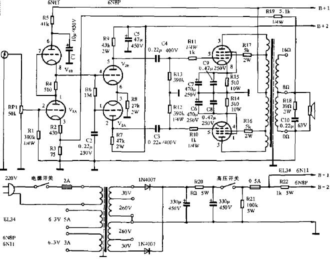
For the production of electronic tube machines, four links of structural design, component assembly, overall layout and installation steps need to be considered. Briefly described as follows:
(1) Structural design
The metal chassis is a bracket for installing all the components of the whole machine, and the resistance-capacitance components are directly welded to the pins as much as possible. If it is difficult, it can be fixed with 8mm wide bakelite strips. The whole machine adopts a fully symmetrical layout and the shortest path design: 220V AC input, fuse, signal input, speaker wiring installation back; high and low voltage switches, volume potentiometer installation front. In order to reduce electromagnetic interference, the power transformer and output transformer are designed with shielding covers.
(2) Component assembly
The power transformer adopts 250VA, double 260V + dual 30V large capacity, small power supply internal resistance; the output transformer requires a large primary inductance, small leakage inductance, small distributed capacitance, low phase shift, 40W push-pull output transformer ; The potentiometer selects a logarithmic 100K dual trimmer potentiometer with low dynamic noise, which can be used in parallel to improve reliability; large-capacity electrolytic capacitors for high-voltage rectification filtering and power supply voltage decoupling require electrolytic capacitors with high withstand voltage and small leakage ; Small capacity capacitors for coupling between circuit stages, polypropylene CBB capacitors with low dielectric loss and good insulation can be selected; resistors use metal film resistors RJ type with high precision and low thermal noise, screen load resistance, cathode The coupling resistance is selected to be more than 2W; the gate leakage, anti-vibration, negative bias, and negative feedback resistance are selected to be small, 0.25W RJ resistors.
(3) Overall layout
1. The positions of the amplifiers at all levels should be arranged in a straight line according to the connection sequence on the circuit schematic, so that the lead between each level is the shortest, and the "ground" currents of all levels flow within the range of this level. It will not flow into other circuits, and cause self-oscillation.
2. The power supply line and the audio signal transmission line should be separated as much as possible; the low-level input amplifier circuit should be as far away as possible from the high-level output circuit; the components that are prone to failure should be installed in a location that is easy to replace.
3. Large loop negative feedback resistors and capacitors should be installed at the output end of the output transformer.
4. The wiring of the filament is made of double-stranded wire, and the two wires are twisted together. When the current in the opposite direction is passed, the alternating electric field radiated will cancel each other out.
5. The lead wire between the volume potentiometer to the signal input jack and the center sliding point of the volume potentiometer to the grid of the first stage circuit should be shielded and the lead wire should be as short as possible.
6. How to properly arrange the ground wire and handle the ground wire branch problem is also the main method to eliminate circuit hum and self-excited interference. This machine adopts three-level tandem grounding bus arranged in "one-point grounding". See Figure 2: 
(2) According to the signal transmission direction, connect the grounding points of the input stage, the inversion driving stage and the final stage power amplifier in series, and the signal grounds of these three stages are insulated from the chassis.
(3) "One-point grounding" is set on the final power amplifier grounding point, which includes four grounds: signal ground, shielding ground, power rectification, filtering ground, and chassis ground. The filament ground connected to "one-point grounding" needs to be tested and set At the pre-stage grounding point.
(4) Installation steps
Fix the power transformer, power rectifier and filter resistance-capacitance components on the chassis, connect them according to the power supply voltage supply diagram, and check whether the power supply part is normal and whether the high and low voltages of each group are correct.
Arrange the ground bus, filament wire, power supply voltage high and low voltage switch wiring, and install the output transformer, the five-pole power tube EL34, and the reverse phase push double triode 6N8P. Voltage amplifying double triode 6N11, resistance-capacitance components at all levels. It is required to be installed from level 1 to level 1 in the front stage and connected to level 1 level.
After checking correctly. Finally, the input stage is short-circuited, and the output terminal is connected with 8Ω 15W or 16Ω 16W dummy load. Measure the DC voltage at all levels after power-on, and use an oscilloscope to observe whether the whole machine is self-excited. If there is self-excitation, it means that the lead wires of the primary P1 and P2 terminals of the output transformer are wrongly connected, and the phases are reversed. The two ends of P1 and P2 can be reversed to change the loop phase to eliminate self-excitation.
3. Circuit debugging
After the welded tube amplifier is powered on. First of all, it should be measured whether the working point of each tube is working in the best state. Otherwise, it is necessary to adjust the working point of the tube.
Adjust the working point, according to the data provided in the "electron tube" manual, as the basis of the electronic tube machine circuit debugging. The characteristics of EL34, 6N8P and 6N11 tubes selected by this machine are shown in Table 1. 
(1) Debugging of the first level SRPP circuit
When 6N11 double triode is used for voltage amplification circuit class A work, the working current should be between 30% and 60% of the maximum screen current of 6N11 tube, that is, 0.48mA-1.2mA. The screen pressure of the upper tube should be half of the power supply voltage Ecc = B +. For the SRPP circuit, each tube is divided into half voltage, and the lower tube screen voltage should be 25% of the power supply voltage. The debugging method of the working point is:
1. By measuring the screen voltage of the lower tube V1a. See if it is half of the screen voltage of the upper tube V1b. Measure the screen voltage of the upper tube V1b to see if it is half of the power supply voltage B +. Just adjust the resistance value of the screen load resistor R5 of the upper tube V1b. When the resistance of the screen resistor R5 is used relatively high, the distortion is small. But at this time, the rectified output must have a higher voltage.
2. By measuring the voltage on the cathode resistance (R2 + R3) of the lower tube V1a, it can be converted into the screen current Ia. As long as the cathode resistance (R2 + R3) and R4 of the upper and lower tubes are adjusted at the same time, the screen current of the 6N11 lower tube V1a can be adjusted.
In order to obtain the lowest distortion and a larger dynamic range. The performance of the two transistors of 6N11 is required to be symmetrical, and the cathode resistance of the two transistors of 6N11 is equal, that is, R2 + R3 = R4.
The first stage adopts SRPP circuit playback effect is really good, but it has two shortcomings: First, the first and second stages use direct coupling, the first and second working points need to be adjusted together; second, when the input signal voltage is too high The second-stage inversion driving circuit will have a grid current, so the input signal voltage must not be large.
(2) Debugging of the second-stage inverter drive circuit
The adjustment of the inversion driving stage is very important. Whether the output signals of the upper and lower tubes are symmetrical and equal is related to the maximum output power and distortion of the whole machine. Because of the different state of the circuit, under normal circumstances the load resistance of the tube panel load R7 should be 10% greater than the resistance of the upper tube panel load resistor R9. The two-tube cathode coupling resistance R8 is 10-20kΩ, the two-tube screen load resistance R7, R9 is 20-50kΩ, the adjustment method is very simple:
1. By adjusting the load resistance of the screen electrodes of the upper and lower tubes, make the voltage of the screen electrodes of the upper and lower tubes equal. When the load resistances of the top and bottom of the machine are 43kΩ and 47kΩ respectively. The screen pressure of the two tubes is 190V, and the two output signals at the output end of the inverting driving stage are symmetrical and equal.
2. By adjusting the resistance value of the cathode coupling resistance of the two tubes, the screen current of each tube is about 4.3mA, and the output voltage of the two tubes can be balanced. Or send a 1kHz 200mV sinusoidal signal at the input of the first stage. When the volume potentiometer is at the maximum volume, reverse the resistance value of the phase-stage cathode coupling resistance, and observe the screen pressure waveform of the upper and lower tubes of the 6N8P with an oscilloscope. See if the amplitude is symmetrical. There is no distortion. When the cathode coupling resistance of this machine is R8 = 27kΩ, the screen current of each tube is 3mA.
(3) Debugging of the final super-linear push-pull circuit
The purpose of the adjustment of the push-pull amplifier circuit is to balance the two push-pull power amplifier tubes of the EL34, and the grid bias voltage and the screen current of the two power amplifier tubes must be equal.
If the bias voltages of the two tubes are not equal, the size of the grid resistors R12 and R13 can be adjusted; if the screen currents are not the same, the size of the resistance values ​​of the cathode resistors R14 and R15 of the two tubes can be adjusted. The size of the screen stream should be appropriate. Small screen flow is beneficial to the life of the electron tube.
Pay attention when adjusting, do not exceed the maximum screen consumption Pamax = 13.5W of EL34 power amplifier tube. When working in Class A. The screen pressure Ua screen flow Ia of the power amplifier tube is equal to its static screen consumption. After exceeding, the screen electrode will be red, and the amplifier tube will burn out after a long time.
When adjusting the screen current, you should also pay attention to the change of the B + voltage. If the screen current is large, the B + voltage decreases a lot, which means that the power supply has insufficient margin or the power supply internal resistance is large. If the difference in screen flow between the two tubes is large, it means that the power amplifier tubes are not paired and one should be replaced. The adjustment method of the working point of the push-pull amplifier circuit is: adjust the resistance values ​​of the cathode resistances R14 and R15 of the two tubes. The resistance values ​​of R14 and R15 are determined according to the sum of the grid bias voltage, screen current and curtain grid current of the EL34 power amplifier tube.
By changing the position of the ultra-linear connection, different magnitudes of negative feedback of the grid can be obtained. Through the audition, the position of the best taps SG1 and SG2 of the super-linearity are determined. The EL34 screen current of this machine is adjusted to 33mA, and its screen voltage is 240V. The output transformer primary SG1 and SG2 taps are on terminals 6-7.
(4) Adjustment of large loop negative feedback
Between the cathode voltage divider resistance of the first-stage SRPP circuit and the output end of the last-stage output transformer, increasing R17 = 5.1K 0.25W is the large-loop negative feedback resistance. Because the feedback of the tube amplifier circuit is voltage, the amount of negative feedback should not be too large, generally about 6dB, and the negative feedback of this machine is adjusted to 4.7dB. After the whole machine has large-loop negative feedback, it will reduce harmonic distortion, broaden the frequency response, and make the listening feel better. The adjustment method is mainly to change the value of the negative feedback resistor R17. The amount of feedback is determined according to the sound effects such as sound field, positioning, sweetness of the human voice, and sense of music, subject to the satisfaction of hearing.
If the negative feedback circuit makes a scream as soon as it is connected, this is because the polarity of the negative feedback is reversed. As long as the negative feedback cable is connected to the other end of the output transformer, this end can be changed to ground. Some negative feedback loops are connected in parallel with a small capacitor. If the value of this capacitor is not selected properly, it may cause distortion or self-excitation. Therefore, when this phenomenon is found, simply remove the small capacitor.
(5) Whole machine test
After the amplifier circuits at all levels are debugged, the output terminal is connected to a 8Ω dummy load, the input terminal is input with a 1kHz, 200mV sine wave signal, adjust the volume potentiometer volume, use SR8 oscilloscope at all levels of the screen, observe the output signal for the maximum undistorted output voltage waveform Under the conditions, measure the voltage amplification of each level. Test results of voltage, current and voltage magnification of electron tubes at all levels. 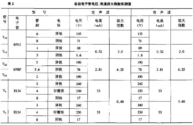
Ensuring Quality Through In-house Production
From design to production, all processes are carried out in our factory. This enables us to closely monitor the quality of all our products - compared to our competitors who outsource their production and have little control over QC.
For more information, contact us today.
EL34 tube machine principle, production and debugging
2. Production
(1) All the ground elements of the screen and cathode, grid and cathode circuits of this level may be welded to a ground point nearby.
The content of electronic tube machine circuit debugging. In addition to reducing the noise to an acceptable level and replacing the brand or capacity of the input and output coupling capacitors, the most important thing is to adjust the screen voltage, screen current and negative bias voltage of all levels of tubes to make the tubes work at a suitable working point , So that the charm of each tube can reach a satisfactory playback effect.