Abstract: This design is a digital electronic clock device based on a counter. The main components of the device circuit are the 555 timer, frequency divider, counter, decoder, display, and timing circuit. Decoding instead of mechanical transmission. The LED display is used instead of the pointer display to display the time, which reduces the timing error. This type of watch has the function of hour, minute and second star time. It can also perform time and minute calibration, and the flexibility of chip selection is good. Such an electronic clock implemented with a digital circuit has higher accuracy and intuitiveness than a mechanical clock. This article refers to the address: http://
Led Bulbs are more energy saving than traditional bulbs. They feature with stable performance, long life, high lumen, soft light, top quality, no flashing, no UV or IR radiation, environment-friendly. And their design is more flexible and diverse. LED bulbs using
the existing interface, that is, screw mouth (E26 \ E27 \ E14, etc.),
jack (B22, etc.), and even to meet people's habits to imitate the
incandescent bulb shape. Based on the principle of
LED unidirectional light, the designer has made changes in the
structure of the lamp so that the light distribution curve of the LED
bulb is basically the same as that of the incandescent lamp.
Led Bulbs Mini Led Bulbs,Led Filament Bulb,Led Corn Bulb,Led Emergency Bulb Zhongshan Laidi Lighting Co.,LTD , http://www.idealightgroup.com
Keywords: 555 timer; frequency divider; counter; decoder; display
0 Introduction Digital electronic clock ICs are mostly composed of oscillators, frequency dividers, counters, decoders, and LED displays. Decoding replaces the mechanical transmission, and the LED display replaces the pointer display to display the time, reducing the timing error.
This design is to study the digital electronic clock realized by digital circuit. The overall circuit design is composed of oscillator, frequency divider, counter, decoder, LED display and timing circuit. The electronic clock realized by the digital circuit has higher accuracy and intuitiveness than the mechanical clock, and has a longer service life.
1 The overall design of digital electronic clock The basic components of digital electronic clock are multi-vibrator composed of 555 timer and RC, frequency divider, counter corresponding to "hour", "minute", "second", decoding display, school The time circuit, its block diagram is shown in Figure 1. 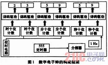
2 Unit circuit design The oscillator is the core of the digital electronic clock. The stability of the oscillator and the accuracy of the frequency determine the accuracy of the digital clock. A crystal oscillator is usually used to form an oscillator circuit. This article uses a multi-vibrator composed of 555. It is an unsteady circuit. After the power is turned on, no external trigger signal is needed, and the circuit state can be automatically changed continuously to generate a rectangular wave output. There are two transient states in this circuit. Capacitor C1 is charged and discharged between (1/3) VCC and (2/3) VCC. The first transient state is: when the power supply is just turned on, the power supply voltage charges C1 through R1 and R2, and the charging time is T1=(R1+R2)*C1; the second transient is YES, and the capacitor C1 passes through the resistor R2. Discharge with the discharge tube, the discharge time is T2 = R2 * C1. Therefore, the oscillation period of the circuit is T=0.7 (R1+2*R2)*C1, and the frequency F=1/T. We can get the desired frequency by changing the values ​​of R1, R2 and C1. This circuit is shown in Figure 2. 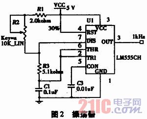
The time base signal of the digital electronic clock is 1 Hz, and the 1 kHz signal generated by the 555 timer must pass through the frequency divider to obtain a 1 Hz signal. The frequency divider is also a counter. The splitter used in this design has two functions: one is to generate a standard 1 Hz pulse signal; the other is to provide a correction signal for the correction circuit. Because the 74LS90 is a two-to-five-decimal counter, the above functions can be realized by three-stage counter cascading, that is, three-chip cascading can obtain the desired frequency signal. The circuit diagram is shown in Figure 3. 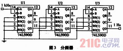
The digital electronic clock requires two 60-input counters as the "minute" and "second" counters, respectively, and a 24-digit counter for the "hour" counter. The 60-digit counter is implemented by a 74LS90 and a 74LS161 cascade. The 74LS161 is used as a "second counter" unit, so it is designed as a decimal counter, which is implemented here using the feedback preset method. That is, when the counter counts to 1001, the QA terminal and the QD terminal of the 74LS161 are respectively connected to the input terminal of a NAND gate, and the output terminal of the NAND gate is sent to the preset terminal LD, so that the decimal counting can be realized. The ten bits of the "second counter" are implemented with 74LS90, so it is designed as a hexadecimal counter and implemented by feedback clearing. That is, when the counter counts to 0110, the QB terminal and the QC terminal of the 74LS90 are respectively connected to the input end of an AND gate, and the output terminal of the AND gate is sent to the clear terminals R01 and R02, thereby realizing the hexadecimal counting function. . Its circuit diagram is shown in Figure 4. 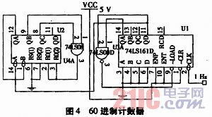
In this design, the 24-digit counter is implemented by two 74LS90 cascades. First set the two 74LS90 to a decimal counter, cascade them, and then use the feedback zero method to achieve 24 counts.
Decoding is to translate the given code. This design translates the 8421BCD code output by the hour, minute and second counter into the corresponding decimal number and displays it through the display. Usually the display is used with the decoder. We chose the seven-segment decoding driver 74LS48 and the common cathode digital tube.
At the beginning of the timing, it must be calibrated to the standard time. This function is performed by the timing circuit. This circuit implements calibration of time and minute. The principle of the school time is to introduce a fast pulse signal that is many times more than the conventional timing to the clock circuit of the school, so that the timing circuit can quickly reach the standard time.
3 Simulation of digital electronic clock (1) Simulation of multi-resonant circuit This circuit is composed of 555 timer and RC. During the simulation, observe the output of the 555 timer with an oscilloscope, and adjust the parameters of the variable resistor in the circuit to obtain a rectangular pulse wave of 1 kHz.
(2) Simulation of counting and display circuit This part is composed of two 60-ary counters, a 24-digit counter, a decoder and a display. Connect the circuit and simulate it according to the design principle. Give the 60-counter a 1 Hz pulse. Observe the display of the digital tube to see if the counter is timed normally, and carry the position to the minute counter when the second counter counts up to 60. After the minute counter has expired 60, the hour counter is rounded.
(3) Simulation of the timing circuit When the counter starts to work, if the circuit display does not match the standard time, it needs to be timed. Two switches are used in this design to perform hour and minute calibrations. When the switch is turned on, the circuit works normally; when the switch is closed, the timing is performed. The frequency of the school time is set to 1 Hz.
4 Digital electronic clock debugging circuit board This system is based on oscillator, frequency divider, counter, decoder, LED display, and timing circuit. The entity diagram is shown in Figure 5. 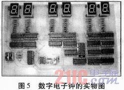
5 Conclusion This design is an electronic clock device for pure digital circuits. The 1 kHz signal is generated by the 555 timer, and the 1 Hz standard signal is obtained after the frequency divider. This signal directly determines whether the electronic clock travels accurately. The second counter and the minute counter are both 60-bit gauges designed by 74LS90 and 74LS161. The hour counter is a 24-digit counter designed by the 74LS90. Since the count initial time is inconsistent with the standard time, a timing circuit is also designed in the circuit. This design can also be extended with additional circuits, such as timekeeping circuits and display dates. 