Electromagnetic interference (EMI) has become a part of our lives. Do you want to deal with it? Many people believe that the widespread use of electronic solutions is a good thing because it brings comfort and safety to our lives and brings medical services to us. However, these solutions also produce EMI signals with electronic hazards. The source of EMI signals is varied. These sources include some of the electronic devices that are common to us. Cars, trucks, and heavy vehicles are themselves generators of EMI signals. The problem is that these EMI sources are in the same position as the sensitive electronic circuits - inside the vehicle. This proximity will affect audio equipment, automatic door controllers, and other devices. Such EMI noise present in vehicles is foreseeable. But what about the mobile phones that people in our 21st century use all the time? Every electronic device has its advantages and disadvantages. Today, the use of mobile phones allows us to easily connect with friends, family and business partners from anywhere. However, the phone also generates EMI signals, and this is only the beginning of the problem. The development of mobile phones has surpassed its basic phone functions and has more smart phone functions. This EMI noise is completely unpredictable for interference with surrounding equipment and circuitry. Mobile phones rely on high RF energy to work. Even if the regulations are met, the phone may become an unintentional source of EMI that interferes with the work of sensitive surrounding equipment. Printed circuit boards, clock circuits, oscillators, digital circuits, and processors also become internal EMI sources. Some electromechanical devices that perform switching operations on currents generate EMI during critical operations. These EMI signals do not necessarily have a negative impact on other electronic devices. The spectral composition and intensity of the EMI signal determines whether it will have an unexpected impact on sensitive circuits. You can simplify the spectral components of a digital signal to its frequency and rise time. The clock or system frequency establishes the time reference of the circuit, but its edge rate forms interference harmonics. Figure 1 shows the spectral components of a 10 MHz square wave. The 10 MHz signal has an edge rate of 10 ns. Note that the magnitude of these harmonics in Figure 1 decreases with frequency. In general, the potential EMI of this signal is: fMAX = 1/(Ï€x tRISE) Equation 1 The equation for the 10 ns edge rate results in approximately 31.8 MHz. The graph shows that the last significant harmonic appeared at 30 MHz. At the same time, the equation at 1 ns edge rate shown in Figure 2 results in a maximum frequency of 318 MHz. If your circuit is susceptible to frequencies generated in the 318 MHz band, EMI harmonics can cause interference in your circuit. Figure 1 Analog EMI signal for 10 ns rise and fall time signals Figure 2 1 s EMI signal for analog EMI signal In fact, it is better to eliminate the interference signal at its source without letting it pass through your circuit. As far as vehicles are concerned, more and more components are made of plastic. However, this is a problem when you want to find a low impedance ground or implement signal shielding. Once the signals are “freeâ€, they “wander around†and enter your sensitive system, which can cause serious damage.
Weak cables refer to cables used for security communications, electrical equipment, and related weak current transmission applications.
Wire and cable refers to materials used for power, communications, and related transmission purposes. "Wire" and "cable" do not have strict boundaries. Usually, the product with a small number of cores, a small product diameter, and a simple structure is called a wire. A wire without insulation is called a bare wire. Others are called cables. A conductor with a larger cross-sectional area (greater than 6 mm2) is called a large wire. Small (less than or equal to 6 mm2) is called a small wire, and an insulated wire is also called a cloth wire. Low Current Cables,Charter Cable,Spectrum Cable,Coaxial Cable Jiangsu QiSheng Cable Co., Ltd. , https://www.shuaihe-cable.com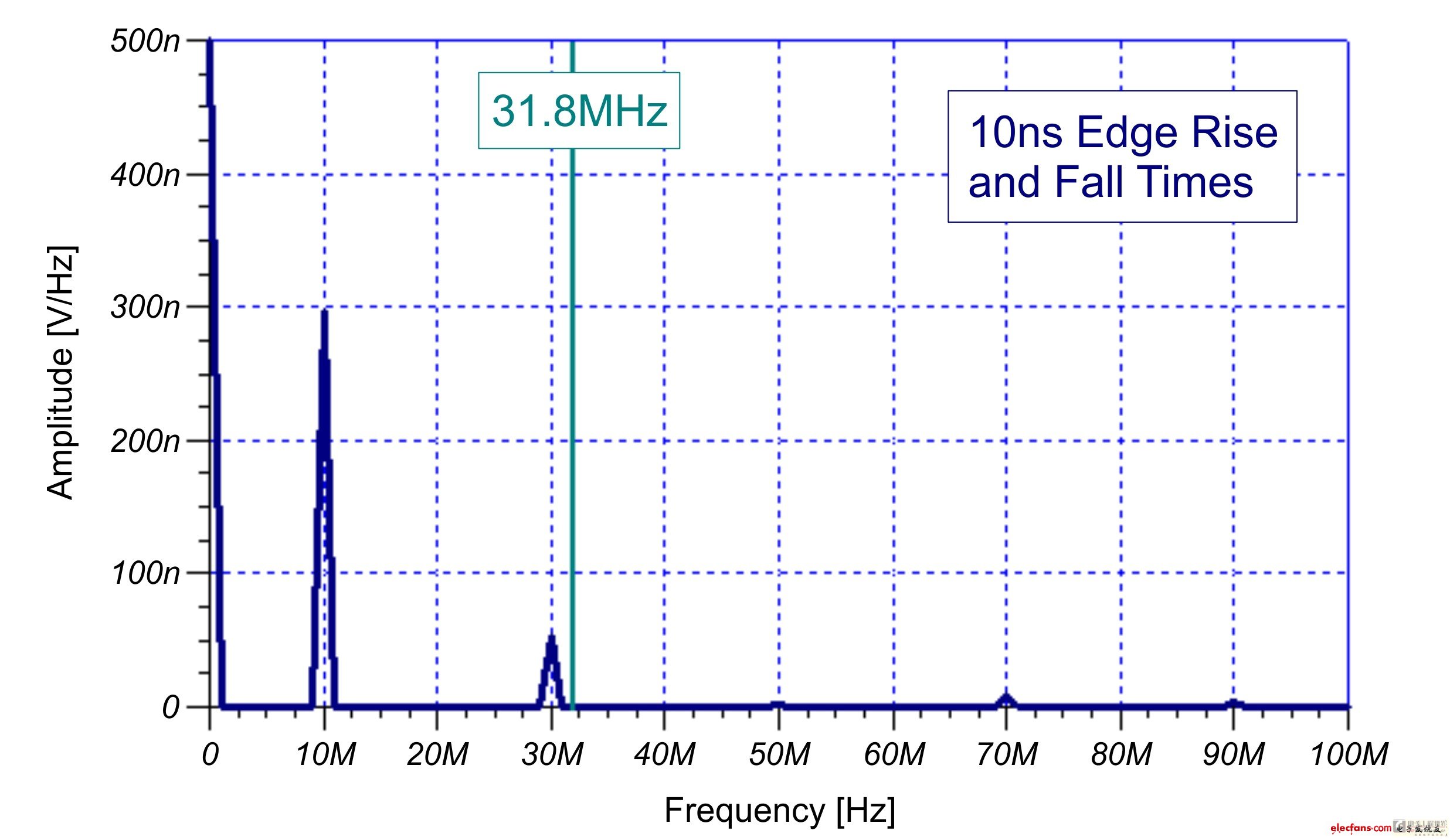

Wire and cable include bare wires, electromagnetic wires and insulated wires for electrical appliances, power cables, communication cables and optical cables.
1, the content included in the product name
(1) Product application or size class name
(2) product structure materials or types;
(3) Important or additional features of the product
Basically named in the above order, sometimes to highlight important or additional features, features are written before or before the corresponding structure description.
2, the order of the structure description
The product structure is described in terms of the principle from the inside to the outside: Conductor-->insulation-->inner sheath-->outer sheath.
3, simplified
Some structures describe writing or abbreviations without causing confusion.
Composition
From the inside to outside by the inner conductor, insulation, outer conductor and sheath;
Inner conductor: Since the attenuation is mainly caused by the resistance of the inner conductor, the inner conductor has a great influence on the signal transmission
Insulation: Impact attenuation, resistance, return loss and other properties
Outer conductor: loop conductor, shielding effect
Video signal transmission generally adopts direct modulation technology and takes the form of baseband frequency (about 8MHz bandwidth). The most common transmission medium is Coaxial Cable; coaxial cable is specially designed to transmit video signals, and its frequency loss, image distortion, The amplitude of image attenuation is relatively small, which can well complete the task of transmitting video signals.
Commonly used special SYV75 ohm series coaxial cable; commonly used model is SYV75-5 (its non-relay transmission distance for the video signal is generally 300-500m); when the distance is long, SYV75-7, SYV75-9 must be used Axle cable (In actual engineering, the relayless transmission distance of the thick cable can reach 1km or more)
The communication cable is generally used in an imaging device equipped with an electric pan/tilt head and an electric lens, and a remote control decoder must be installed in the field when in use; a communication transmission cable between the on-site decoder and the video matrix switching host of the control center is generally adopted. 2-core shielded communication cable (RVVP) or category 3 twisted pair UTP, with a cross-sectional area per core of 0.3mm² ~0.5mm²; the basic principle for selecting a communication cable is that the longer the distance, the larger the wire diameter; RS-485 communication regulations The basic communication distance is 1200m, but in the actual project, the RVV2-1.5 sheath line can be used to extend the communication length to over 2000m.
The control cable usually refers to the multi-core cable used to control the PTZ and the electric variable lens; one end of the control cable is connected to the PTZ of the controller or the decoder, and the electric lens controls the terminal, and the other end is directly connected to the PTZ. On the corresponding terminals of the electric lens, the control cable provides DC or AC voltage, and the distance is generally short (sometimes less than 1m). There is basically no interference problem, so no Shielded Cable is required.
Commonly used control cables mostly use 6-core or 10-core cables, such as RVV6-0.2, RVV10-0.12; 6-core cables are connected to the top, bottom, left, right, automatic, and public 6 terminals of PTZ respectively, 10 cores In addition to the six terminals of the pan-tilt head, the cable includes four zooming, focusing, aperture, and common terminals of the electric lens; in the monitoring system, the control cable from the decoder to the pan/tilt head and the lens is short due to the short distance. Generally do not make special requirements; and from the central control room controller to the pan and tilt and electric lens distance is as small as tens of meters, as many as several hundred meters, the control cable needs to have certain requirements, that is, the diameter of the wire should be thick, such as selection RVV10-0.5, RVV10-0.75
Audio Monitoring Cable generally uses 4-core shielded communication cable (RVVP) or Category 3 twisted pair UTP, with a cross-sectional area of 0.5 mm² per core;
The audio signal of the monitor head in the monitoring system is transmitted to the central control room and is a point-to-point wiring method. It is transmitted with high voltage and low current, so an unshielded 2-core cable can be used, such as RVV2-0.5.
RVV2*0.3 (signal line) and RVV4*0.3 (2-core + 2-core power) cables are generally used between the front-end detector and the alarm controller; the two controllers are generally used between the alarm controller and the terminal security center. Signal line
Whether the signal line is shielded or twisted or it is a common sheathed cable, it needs to be determined according to the requirements of various brands of products; the rough specification of the signal line diameter is determined according to the distance and quality of the alarm controller and the center; alarm control The power supply of the device generally uses local power instead of centralized power supply in the control room. The line is short, generally adopting RVV 2×0.5" or above specifications; the perimeter alarm and other public area alarm devices generally use centralized power supply mode, and the line is longer. RVV2*1.0" or above specifications are generally used
Cables used in building intercom systems are mostly cables such as RVV, RVVP, SYV, etc.
Has: transmission of voice, data, video images, while cable requirements also reflected in the quality of voice transmission, data transmission rate, video image transmission quality and speed, etc.
Cables that transmit voice signals and alarm signals mainly use RVV4-8*1.0
Video transmission is based on SYV75-5 cable
Some systems must use RVVP cables in the system when they are afraid of external interference or cannot be grounded.
Direct Push-to-Talk Visual Intercom System Line Standard:
Video terminals, two-way audio and remote control unlocking terminals of all indoor units are connected to the door machine in a bus way, but each call line is directly connected to the door machine alone.
--Video coaxial cable SYV75-5, SYV75-3
- Use a 4-core non-shielded or shielded sheath cable (AVVR4, RVV4, or RVVP4, etc.) for the microphone/speaker/unlock cord
- A 2-core jacket wire (AVVR2, RVV2, etc.) for the power cord
-- 2-wire shielded cable for call lines (RVVP2)
Digital coded push-button video intercom system:
- The main line includes video coaxial cable (SYV75-5, SYV75-3, etc.)
- Power cord (AVVR2, RVV2, etc.)
-- Audio/data control lines (RVVP4, etc.)
- Household Signal Line (RVVP6, etc.)