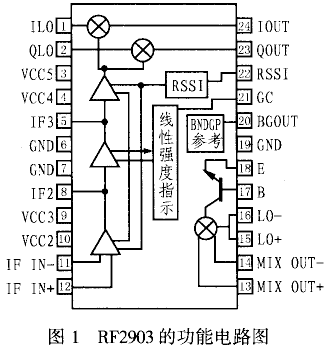
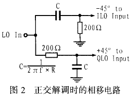
RF2903 is a high-performance spread-spectrum receiving chip of RF Company. It consists of three parts: pre-amplification and mixing at the RF front end, intermediate frequency variable gain control and demodulation. For intermediate frequency signals below 200MHz, The RF 2903 spread spectrum receiver chip can be widely used in spread spectrum communication systems, dual-mode analog / digital receivers, POS terminals, handheld communication systems, and 2.4GHz ISB broadband receivers. The main features of RF 2903 are as follows: ◠Can work under the voltage of 3 ~ 6V; ◠With FM, PM and quadrature demodulation functions; ◠With linear analog gain control and RSSI strength indication function; ◠The intermediate frequency range is 10 ~ 200MHz, and the radio frequency range is 150 ~ 1000MHz; ◠Normal working temperature range: -40 ~ + 85 ℃; ◠The conversion gain can reach more than 94dB; ◠Package form is SOP-24. The internal schematic diagram and pin arrangement of RF2903 are shown in Figure 1. Table 1 lists the functions of each pin of RF2903. As can be seen from Figure 1, the RF front end of RF 2903 has three RF amplifiers and down-converters. It also contains three unit circuits with linear gain control and received signal strength indication (RSSI) functions. In addition, there is a quadrature inside RF 2903 Demodulator. 2.1 RF amplification and down conversion of the RF front end The RF amplification and down-conversion of the RF 2903 RF front-end uses differential input, and they all have low-noise amplification. If the differential input mode is not used, one of the input terminals can be left floating or connected to the power supply Vcc. In order to make the system design flexible, the RF front-end can adopt different design methods. In order to ensure that the RF 2903 can reliably receive the signal within its receiving sensitivity range, the LNA and the mixer should be adjusted to their maximum gain and minimum noise figure. This can be achieved by using its external transistor plus an inductor and capacitor. In order to improve the sensitivity of the system, a low-noise amplifier (LNA) can be added, which can also increase the noise figure of the entire system. 2.2 Intermediate frequency amplifier with linear gain control and RSSI The intermediate frequency part of RF 2903 is composed of three identical intermediate frequency amplifiers with linear gain control and RSSI. When the RF 2903 is applied to a linear system (such as a direct sequence spread spectrum receiver), gain control will keep the signal level at a certain level. When it is used in a non-linear system (such as FM or frequency hopping receiver), its gain can always remain at its maximum state. 2.3 Gain control The gain control of the RF 2903 can be achieved by adjusting one pair of differential amplifiers and leaving the other pair of amplifiers inoperative. Because the two differential input pairs of the intermediate frequency amplifier are mutually conductive, that is, when the current flowing to one pair is larger, the current flowing to the other pair is smaller. 2.4 Received signal strength indication Through RSSI, the strength of the received signal can be known, which changes with the change of the control gain. In this way, when doing system design, you can use RSSI to design a feedback loop to keep the output signal stable. 2.5 Quadrature demodulator The quadrature demodulator of RF 2903 is composed of two mixers and can be driven differentially by the output of the intermediate frequency amplifier. It must be noted that its input signal must have a phase difference of 90 °, which can be achieved by the simple phase shift circuit shown in Figure 2. Since the LO input is directly connected to the base of the input transistor, an external pull-up resistor is required. The mixer output can be buffered by the emitter of the next stage, so that it can directly drive the low-resistance filter. The chip's own bandgap reference voltage output can be used to correct the circuit. In this process, the chip is not sensitive to changes in temperature and power supply, so it can work normally under the power supply condition of 2.7V to 5.5V. The modulation and demodulation methods currently used in spread spectrum communication are mainly orthogonal modulation and demodulation. Figure 3 shows the application of orthogonal demodulation of RF 2903 in a spread spectrum system receiver. It is worth noting that the mixer output and the intermediate frequency input pin, because a single-ended filter is used, so there is no need to use the output of the balanced filter and the input of the balanced intermediate frequency part, but only one input and one output. In the figure, pin 14 is used as the output of the mixer, and pin 11 is used as the intermediate frequency input. Of course, 13 feet and 12 feet can also be used. Because there is a filter at the output of the mixer and the input of the intermediate frequency, when high isolation is required, it is recommended to use pins 11 and 14 instead of pins 12 and 13. After testing, at 900MHz, the receiving sensitivity of RF 2903 can reach -100dB. As we all know, FSK modulation and demodulation are mainly used in frequency hopping systems. Figure 4 shows the application circuit of RFSK demodulation in RF 2903 in frequency hopping communication system receivers. It can be seen from the figure that its peripheral circuit is similar to its peripheral circuit in quadrature demodulation application, but there are some changes at the signal input terminal. When RF2903 is used for FSK demodulation, its gain control can be adjusted to the maximum, because in this case, the intermediate frequency amplification does not need to meet the linear conditions. Finally, it should be noted that if you do not use the demodulation function of RF2903, but add a DC voltage to the LO input, then RF2903 can also be used as an ordinary amplifier. RF2903 is an ultra-low-cost dedicated receiving chip mainly used for DS-SS and FH-SS. It has the characteristics of wide operating frequency band, low operating voltage, flexible configuration, and wide application range. Therefore, RF 2903 is very suitable for application in the field of wireless communication. Neckband Earphones,Neck Earphones,Best Neckband Earphones,Wireless Neckband Earphones Dongguang Vowsound Electronics Co., Ltd. , https://www.vowsound.com The gain can reach 90dB, the gain can be achieved by an analog voltage. The RF 2903 contains a received signal strength indicator circuit that can perform energy level detection. Since there are two symmetrical mixers in the RF 2903, it is very advantageous for quadrature demodulation. Of course, it can also be used for FM / FSK and AM demodulation, but when used for AM detection, an external detection circuit is required.
1 Main features and functions of RF 2903
2 Pin function and internal circuit principle
Table 1 RF2903 pin functions Pin number Pin definition Function description 1 ILO I channel demodulation mixer LO input 2 QLO Q channel demodulation mixer LO input 3 VCC5 Power supply for I and Q two-channel demodulation mixer 4 VCC4 Power supply for IF3 amplifier 5 IF3 IF2 output / IF3 input 6, 7 GND Ground 8 IF2 IF1 output / IF2 input 9 VCC3 Power supply for IF2 amplifier 10 VCC2 Power supply for IF1 amplifier 11, 12 IF IN-, IF IN + IF1 amplifier differential input 13, 14 MIXOUT +, MIXOUT- RF mixer output 15, 16 LO +, LO- Differential input of RF mixer 17 B RF input pin 18 E Emitter of RF transistor 19 GND Ground 20 BG OUT Bandgap reference voltage output twenty one GC Analog gain control pin twenty two RSSI Accept signal strength indication twenty three Q OUT Q channel demodulation mixer baseband output twenty four I OUT I channel demodulation mixer baseband output 
image 3
3 Application of RF 2903 in spread spectrum communication
Figure 4
4 Conclusion