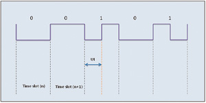
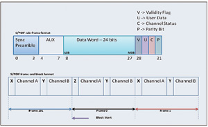
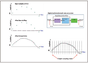
Today's audio design challenge is how to simulate actual sound and transmit it through various audio devices. Sound can come from any direction. In fact, our brain can calculate and perceive the source of sound. For example, when a fighter flies from one point to another, the sound it produces actually comes from countless location points. However, it is impossible for us to reproduce this audio experience with countless speakers. Using multi-channel, multi-speaker systems and advanced audio algorithms, the audio system can mimic real sounds in a brilliant way. These complex audio systems use ASIC or DSP to decode multi-channel encoded audio and run various post-processing algorithms. The greater the number of channels, the higher the memory and bandwidth requirements, which requires the use of audio data compression technology to encode and reduce the data to be stored. These techniques can also be used to maintain sound quality. With the development of digital audio, there are also audio standards and protocols, whose purpose is to simplify the transmission of audio data between different devices, for example, between audio players and speakers, and between DVD players and AVRs, without having to convert the data to Analog signal. This article will discuss various standards and protocols related to the audio industry, as well as explore the audio system structure of various platforms and various audio algorithms and amplifiers. Standards and protocols S / PDIF standard-This standard defines a serial interface for transmitting digital audio data between various audio devices such as DVD / HD-DVD players, AVRs, and power amplifiers. When transmitting audio from a DVD player to an audio amplifier via an analog link, noise is introduced, which is difficult to filter out. However, if a digital link is used instead of an analog link to transmit audio data, the problem will be solved. Data can be transferred between different devices without converting to analog signals, which is the biggest advantage of S / PDIF. The standard describes a serial, unidirectional, self-provided clock interface that can interconnect digital audio equipment for consumer and professional applications that use linear PCM encoded audio samples. It is a single-wire, single-signal interface that uses biphase mark coding for data transmission, and the clock is embedded in the data and recovered at the receiving end (see Figure 1). In addition, the data is independent of polarity, so it is easier to process. S / PDIF is developed from the AES / EBU standard for professional audio. The two are consistent at the protocol layer, but the physical connectors from XLR to electrical RCA jacks or optical TOSLINK have changed. Essentially, S / PDIF is a consumer version of AES / EBU format. The S / PDIF interface specification is mainly composed of hardware and software. Software usually involves the S / PDIF frame format, and hardware involves the physical connection medium used for data transmission between devices. Various interfaces for physical media include: transistor and transistor logic, coaxial cable (75Ω cable connected with RCA plug) and TOSLINK (a type of optical fiber connection). Figure 1 S / PDIF bi-phase mark coding stream S / PDIF protocol-As mentioned above, it is a single-wire serial interface with a clock embedded in the data. The transmitted data is encoded with bi-phase mark. The clock and frame synchronization signals are recovered together with the bi-phase decoded data stream at the receiver. Each data bit in the data stream has a time slot. The time slot starts with one transition and ends with one transition. If the transmitted data bit is "1", a transition will be added in the middle of the time slot. Data bit "0" does not require additional transitions. The shortest interval between transitions is called the unit interval (UI). S / PDIF frame format-first drive the least significant bit of the data. Each frame has two subframes, which are 32 time slots, a total of 64 time slots (see Figure 2). The subframe starts with a preamble, followed by 24 bits of data, and ends with 4 bits carrying information such as user data and channel status. The first 4 slots of a subframe are called preambles and are used to indicate the start of subframes and blocks. There are three preambles, and each preamble contains one or two pulses with a duration of 3UI, thus breaking the biphase encoding rule. This means that the pattern cannot exist elsewhere in the data stream. Each subframe starts with a 4-bit preamble. The start of the block is represented by the preamble "Z" and the start of the subframe channel "A". The preamble "X" indicates the start of the channel "A" subframe (different from the start of the block), and the preamble "Y" indicates the start of the channel "B" subframe. Figure 2 S / PDIF subframe, frame and block format I2S bus-In today's audio systems, digital audio data is transmitted between various devices within the system, such as between codecs, DSPs, digital IO interfaces, ADCs, DACs, and digital filters. Therefore, in order to enhance flexibility, there must be a standard protocol and communication structure. The I2S bus specification developed specifically for digital audio is now used by many IC manufacturers. It is a simple three-wire synchronization protocol that includes the following signals: serial bit clock (SCK), left and right clock or word selection (WS), and serial Row data. The WS line indicates the channel being transmitted. When WS is at logic high (HI) level, the right channel transmits; when WS is at logic low (LO) level, the left channel transmits. The transmitter sends data in binary, first complementing the MSB. Almost all serial ports of DSP use I2S as one of the serial port modes. The audio codec also supports this mode. Sampling rate converter (SRC)-This is an important part of the audio system. Sampling rate conversion can be achieved either by software or by the on-chip hardware of some processors (see Figure 3). It is mainly used to convert data from one clock domain with a specific sampling rate to another clock domain with the same or different sampling rates. Figure 3 Four different stages of the sampling rate conversion process Audio can be encoded at different sampling rates, and other tasks are performed by the codec. In some cases, the main clock of the codec needs to be changed to support a specific sampling rate. When converting from audio with a certain sampling rate to audio with a different sampling rate, it is not easy to change the main clock in real time, and sometimes it is impossible to complete because of the need to change the hardware on the circuit board. Therefore, the sampling rate conversion is generally performed before driving the data to the codec. In this way, the sampling rate of the codec does not need to be changed and can be kept constant. The serial port sends audio data at the sampling frequency 1 to the SRC and codec at the other end, and then reads the audio data from the SRC at the sampling frequency 2. SRC is divided into two types: synchronous SRC and asynchronous SRC. The output device connected to the synchronous SRC is a "slave", and the device connected to the asynchronous SRC is a "master". "Host" refers to a device that drives SCK and frame synchronization signals. SRC uses an interpolation filter and a zero-order holder (ZOH) with an extremely high output sampling rate to convert discrete-time signals into continuous-time signals. The interpolated value is fed to ZOH and asynchronously sampled at the output sampling frequency of Fs out.
Yuhai company is engaged in produce high performance Piezoelectric Elements,
Piezoelectric Rings For Ultrasonic Machining Custom Hifu Piezo Parts,Hifu Ultrasonic Focusing Part,Piezo Crystal For Hifu,Cheap Hifu Transducer Zibo Yuhai Electronic Ceramic Co., Ltd. , https://www.yhpiezo.com