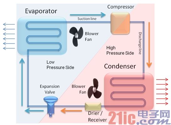
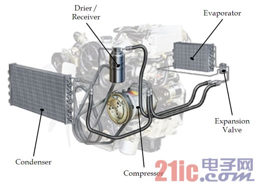
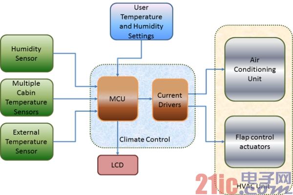
Heating, ventilation and air conditioning (HVAC) technology makes the interior and car cab comfortable. HVAC promotes the management of a comfortable temperature environment inside the cab by controlling the cold/hot temperature. This article refers to the address: http:// In the past, air conditioning in cars was an important feature, but even in entry-level cars, air conditioning has become standard equipment. The need for greater comfort and luxury has led to the development of on-board temperature environmental control systems. The main purpose of the automotive temperature environmental control system is to manage the temperature of the designated area to make passengers feel comfortable. In the early 1960s, cars used HVAC for the first time, and this configuration is currently available in most high-end cars. It is a complex system consisting of mechanical/electronic switches or knobs on the front end. The rear end of the system includes one or more blower motors, actuators (for fresh air circulation control, air flow control, and temperature control) and a refrigeration unit with a number of ducts through which air is delivered to the cab. The basic working principle of the HVAC unit is conduction and convection. Depending on the pressure change, heat is transferred from the low temperature zone in the vehicle to the high temperature zone. This heat transfer process is called cooling. Figure 1 shows a cycle diagram of the complete refrigeration process. Figure 1: Refrigeration cycle diagram. Evaporator: evaporator Compressor: Compressor Suction line: suction tube Blower Fan: Fan Low Pressure Side: Low pressure side High Pressure Side: High pressure side Dischargeline: discharge pipe Condenser: Condenser Expansion Valve: Expansion valve Drier/Receiver: dryer/receiver The air conditioning system consists of five main components: Evaporator 2. Compressor 3. Condenser 4. Receiver / dryer 5. Expansion equipment The five main components are located in two pressure zones: the high pressure side including the condenser and the receiver/dryer, and the low pressure side being the air conditioning evaporator. The dividing point between high pressure and low pressure is divided by a compressor and an expansion valve. Each component of the HVAC system is discussed in detail in the next section (see Figure 2). Figure 2: The air conditioning system consists of five main components. Drier/Receiver: dryer/receiver Evaporator: evaporator Condenser: Condenser Compressor: Compressor Expansion Valve: Expansion valve Evaporator The evaporator is a heat exchange device in the refrigeration cycle. Liquid refrigerant (from the expansion tube into the evaporator) has a lower temperature and a lower pressure. When passing through the evaporator coil, the refrigerant absorbs heat in the air blown through the spiral tube and is converted into low pressure, low temperature steam. The liquid refrigerant flows from the bottom of the evaporator to the top to ensure that the liquid refrigerant boils before leaving the evaporator coil. The tasks performed by the evaporator can be summarized as: Absorb heat 2. Let all refrigerants boil into steam The air blown by the blower is cooled by heat transfer and transmitted to the cab through the vent. Because the air conditioner evaporator provides cooling by absorbing heat from the surrounding medium, this can serve a dual purpose when located in close proximity to the vehicle dashboard. It absorbs heat from the air flowing therethrough and also absorbs heat from the interior of the vehicle to maintain the desired temperature. compressor Air conditioning compressors are considered the heart of the central air conditioning unit. The compressor absorbs the vapor refrigerant in the suction line and compresses the steam into high superheated steam. The temperature of the steam is usually 2.5 times higher than the temperature of the outside air. Because heat always flows from heat to cold, the refrigerant must be much hotter than the outside air to carry the heat away from the system. As the refrigerant flows through the compressor, it also carries away heat from the compressor, motor winding heat, mechanical friction, and other heat absorbed in the suction line. Another major task of air conditioning compressors is to generate a refrigerant stream in the system. The tasks performed by the compressor are: Overheating 2. Take away potential heat (condensation) 3. Take away more heat that can be induced (too cold) 4. Generate refrigerant flow Condenser The hot high pressure steam will then enter the condensing coil. The condenser is like an evaporator and is a heat exchanger. Inside the condensing coil, the refrigerant flows from the top to the bottom of the spiral tube. Because the temperature of the refrigerant is much higher than the ambient temperature, it will cool as it passes through the spiral. When the superheated refrigerant reaches the lower third spiral, it is cooled enough to return to the liquid state. This process is called sub-cooling. When the refrigerant is condensed into a liquid by releasing heat, the temperature outside the copper tube becomes very high, and heat is blown out of the system with the help of a blower/cooling fan. In model vehicles, this heated air becomes a source of hot wind in colder climates. To increase efficiency, the placement of the condenser is also important because it is very hot, so the largest exposed surface area is required to ensure faster cooling. Receiver/dryer The receiver/dryer is located in the high pressure section of the system, typically in the conduit between the condenser outlet and the expansion valve inlet, but some may be directly connected to the condenser. The receiver/dryer provides three very important functions: 1. They serve as storage containers for additional refrigerant during periods of low cooling demand. This is the "receiver" function of the receiver/dryer. 2. They contain a filter that traps contaminants inside the A/C system. 3. The dryer/receiver contains a material called desiccant to absorb the moisture (water) that may be produced in the A/C system during manufacturing, assembly or service. This is the "dryer" function of the dryer/receiver. Expansion equipment The expansion device is required to generate a pressure differential of the liquid refrigerant so as to boil it into a gas. The expansion device causes a pressure drop by limiting the flow of refrigerant around the system. Slowing the flow rate of the refrigerant will cause the compressor to evacuate one side of the system. This low pressure gap becomes the "suction side" or "low side" of the system. Automatic temperature environment control Automatic temperature environment control monitors and controls the temperature of a specific space without manual intervention. The passenger on the bus specifies the required cab temperature and humidity. These values ​​are entered through the temperature environment control system, which electronically controls temperature and humidity and maintains user-specified values. The cab temperature can be adjusted without manual operation of turning on/off the AC or sliding the thermal control switch. The automatic temperature environment control mechanism requires a temperature and humidity sensor to be placed in the cab. These sensors automatically read the temperature and humidity values ​​in this area and feed them to the microcontroller (MCU). The MCU then compares these readings to user-defined settings and adjusts the cold/heat accordingly (see Figure 3). Sometimes, all members of the car have to negotiate a temperature setting - some people may feel cold, while others may feel hot. The technological innovation of on-board automatic temperature environment control has evolved into a zone temperature environment control. With this implementation, each member can adjust the temperature of his/her seating area. Each zone in the defined zone has a separate temperature sensor that reads the current temperature of the specified zone. Each temperature sensor data is compared to the temperature set for a particular zone and the corresponding cooling or heating operation is performed. The automatic temperature environmental control system also includes a computer that regulates the entire air system within the cabin. It allows you to adjust the fan speed, the air conditioner compressor to open and the overall air temperature in the cabin. Often, these processes are integrated into the entire computer system of a contemporary car. Figure 3: In an automatic temperature environment control system, the MCU continuously compares the temperature and humidity sensor data in the cabin with user-defined settings and then adjusts the cold/heat accordingly (see Figure 3). Humidity Sensor: Humidity Sensor Multiple Cabin Temperature Sensors: Multi-chamber Temperature Sensors External Temperature Sensor: External Temperature Sensor User Temperature and Humidity Settings: User Temperature and Humidity Settings Current Drivers: Current Drivers Climate Control: Climate Control Air Conditioning Unit: Air Conditioning Unit Flap control actuators: damper actuators HVAC Unit: HVAC Control Unit Each manufacturer has a unique approach to providing each passenger with a perfect temperature environment; however, they all rely on specific similar components, such as additional controls in the driver's HVAC control unit, additional HVAC control in the rear seat area The unit, the individual temperature sensors in each zone, and many additional hidden ducts are used to deliver air when needed, as well as many additional vents – many, many additional vents. For example, the Lexus LX570 has 28 vents. About the author Nitin Gupta is a senior applications engineer with extensive experience in embedded software development for digital multimedia – including the consumer electronics and automotive industries. Manish Jindgar is a senior applications engineer responsible for developing automotive-related reference applications. Ravinder Dasila has been an application engineer in the Freescale Automotive MCU business unit since July 2011 and has been involved in the design of automotive reference solutions.
Our 12v battery pack designed to be chargeable via motorcycle/car cigaretter, capacity range from 2200mah to 10Ah, with wireless heat controller or bluetooth control. Applications widely ranges in heating clothing, heated motorcycle clothing, heated jacket, electric jacket, electric heated clothing, heated coat, heated vest, heated pants, heatgear, electric gloves, heated jacket mens, heated jacket womens.
12V Heated Jacket Battery,Heated Jacket Battery, Heated Coat Battery,Heated Vest Battery Asarke Industry Co., Limited , https://www.asarke-industry.com