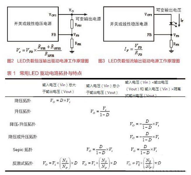
The quality of the LED driver circuit has a significant impact on the normal operation and working life of the LED. The main function of the LED driver circuit is to convert the input power supply into a power supply output suitable for LED driving, to supply power to the LED load, and to match the voltage and current of the LED load according to the working voltage and current requirements of the LED. The main function of the LED driver circuit The LED driver circuit should ensure the constant current operating characteristics of the LED, especially when the power supply voltage changes, the LED operating current can be kept stable. achieve: 1. Ensure that the LED load operating current is stable; 2. Avoid the LED drive current exceeding the maximum rated value, affecting the operational reliability of the LED load; 3. Obtain the required lumen output and ensure the consistency of the LED brightness and luminosity. At the same time, the LED driver circuit should maintain low power consumption, so that the operating efficiency of the LED lighting system can be kept at a high level. Especially in the aspect of dimming, LED can not only achieve 0~100% dimming, but also ensure high luminous efficiency during the whole dimming process, without damaging the working life of the LED, and the gas discharge lamp is difficult. Make it happen. The proportion of component damage in LED luminaires is shown in Figure 1. Among them, the damage rate of LEDs is 10%, the control circuit is 7%, the installation of LED lamps is 31%, and the LED driver is 52%. It can be seen that the damage rate of LEDs in LED lamps is not high, the LED drive circuit failure rate is relatively high at 52%, and 90% of LED lamp failures are not from LEDs (data: Appalachian Lighting Systems). The statistical condition of the data was carried out under the experimental conditions of 29 failure lamps (invalid rate: 0.54%) in 5400 LED lamps. LED driver and related technical requirements The main technical indicators for the LED drive circuit are: maximum output power, allowable operating temperature range, transient on/off operating characteristics, power factor not less than 0.9, input and output voltage variation range, maximum allowable input voltage and current, drive power supply Total harmonic distortion (THD), etc. More advanced LED drivers should have the ability to monitor and report all operating status parameters and intelligent control functions of the LED lighting system, such as the ability to achieve VF values ​​for LEDs without grading, for line voltage drops between LED drivers and LED luminaires Detection and compensation, optical feedback, automatic control of color temperature (CCT) control of white LEDs, and multi-color LED correlated color temperature (CCT) control. Main factors affecting the reliability of LED lighting products In the use of LED driver circuit, attention should be paid to the application of LED driver circuit. For example, pay attention to the use of LED driver circuit, installation method, environmental noise interference, correct use of LED driver circuit and related technical support will improve the reliability of LED driver power supply. helpful. When using the LED driver circuit, it is also necessary to pay attention to the input voltage adaptation range, output voltage and output current variation range of the LED driver circuit, and reasonably manage the LED and its driver circuit. The LED driver circuit should use an appropriate type of electrolytic capacitor. Pay attention to the mechanical stress, vibration resistance, moisture proof and waterproof of the mechanical components of the LED drive circuit. Pay attention to the influence of the optical parameters such as the light output, the illuminating color, and the illuminating angle of the optical components and the LED components on the use environment, pay attention to the anti-UV/chemical resistance of the LED driving circuit and the correct use of the LED driving circuit. Some of the main problems with LED driver circuits are as follows: 1. The general quality LED driver circuit does not use closed loop feedback control technology; 2. Rarely the development of LED driver technology is based on the requirements of complex intellectual property; 3. At present, there are only a few LED driver technologies that use RDM (Remote Deployment Management) technology to achieve remote monitoring of the working status of LED lamps. LED driver circuits have two main effects, direct and indirect, on the LED lighting system. The direct impact is mainly reflected in the cost of the LED driver power supply, the working efficiency of the driving power supply, the EMI operating characteristics, the operational reliability, the regulation characteristics of the LED operating current, the power factor (PF), and the protection operating characteristics of the driving power source (such as overvoltage, Over current, over temperature, etc.) and LED operating ripple current. Indirect effects are mainly reflected in the working efficiency, operational reliability, thermal management characteristics, work safety (such as output isolation or non-isolation) and system cost of LED lighting systems. LED driver circuit common interference Common interferences in LED driver circuits include voltage sags, voltage spikes, undervoltages, overvoltages, transient disturbances of oscillating waves, transient interference from lighting equipment, input surge current or surge voltage interference, common mode noise, differential mode Noise, voltage imbalance, voltage distortion, etc., these interferences will affect the normal operation of the LED lighting driver circuit. In severe cases, the LED lighting driver circuit may be damaged. Therefore, the anti-interference operation of the driver circuit should be considered when designing the LED driver circuit. Performance to ensure reliable operation of the drive circuit. LED constant voltage and constant current drive power supply working principle LED linear constant current (CC) drive power has the characteristics of simple circuit, low component count and low EMI. The LEDs operate in series to ensure that the operating current through each LED is consistent, while the LED constant voltage (CV) driving LEDs in parallel does not ensure that the operating current through each LED is consistent. The power consumption of the linear LED driver circuit can be expressed by the formula (VIN-n×VF)×IF. In the formula, n represents the number of LEDs in the LED load string. In applications where the LED load current is equal to or greater than 350 mA, the linear LED driver circuit is used. The power tube requires a heat sink to increase the cost and volume of the LED driver circuit. (1) LED constant voltage driving power supply working principle The working principle diagram of the LED load constant voltage driving power supply is shown in Figure 2. The output voltage value can be adjusted by adjusting the values ​​of the output sampling resistors RFB1 and RFB2. Since the LED color temperature and output lumen are related to the forward working current of the LED, in order to stabilize the LED light output, it is not suitable to use the constant voltage LED driving mode in practice. (2) LED constant current driving power supply working principle The working principle of the LED constant current driving power supply is shown in Figure 3. The stable LED load operating current is beneficial to the stable LED color temperature and output lumens. Therefore, it is advantageous to use a constant current drive for the LED load in practice. In Figure 3, adjusting the parameters of the current sampling resistor RFB enables adjustment of the LED load drive operating current. If the input supply voltage of the drive power supply is always greater than the output voltage, a more efficient buck converter or Buck converter can be used to provide constant current supply to the LED load. The Buck converter has the advantages of high working efficiency and small heat sink required, but the circuit structure is more complicated, and the operating noise is larger than that of the linear driving circuit. Now the Buck converter's switching operating frequency can be made higher than 1 MHz or higher, so that the peripheral components of the Buck converter are small, and the Buck converter is much smaller than the linear driving power supply. In practice, if the LED load drive power input DC voltage is lower than the operating voltage of the LED load string, an output boost circuit can be used to power the LED load. Inductive output boost (Boost) converters are ideal for constant current LED drive applications where the output current is greater than 350mA, where the output voltage varies with the current in the LED load string. If the DC input supply voltage variation range of the LED load drive power supply varies up and down within the variation range of the LED load string operating voltage, Buck-boost, SEPIC, C'uk or Flyback circuit can be used to drive the LED. load. The topology and characteristics of common LED driver circuits are shown in Table 1. In the formula, D represents the duty cycle of the switching pulse. references: [1]Archenhold G.An Incredible Year for LED's The story so far,Aston Science Park / SSLRC.2007 PPT [2]Tuttle P C.White LED Chromaticity Control-The state of the Art, Transformations in Lighting .2011. DOE Solid-State Lighting R&D Workshop, CREE LED Lighting PPT [3] Lu Qiusheng. LED driver circuit and related technical requirements. Today's Electronic Supplement, 2012(10): 52-56 [4] Lu Qiusheng. SSL lighting technology and progress. Journal of Power Supply, 2011(1): 99-105
3D Led Bulb is widely used in dj lighitng, disco lighting, club lighting, resturant lighting, theme resturant lighting and park decoration lighting. We call the rgb led bulb in different name for different led lighting application, like dj ball, ball 3d, Disco Ball Light Bulb, club led bulb, etc
The 3D LED Bulb can be for indoor and outdoor. We cooperate with other famous design organizations to make a big improvement on LED 3D control technology, and developed many 3D visual products, like the ball string(40mm 3D LED Ball string, 50mm 3D Led Ball string), and the big Magic Led Ball with different size,. The 3D balls control mainly by DMX 512 protocol, and easy to built the led lighting system.
Suppor DMX512 control, address can be manually and automatically set, long transmitting distance of signal and strong anti-interference.
3D LED Bulb Built-in high precision constant current driver IC, LED luminous efficiency is good and uniform color.
Apply superior quality high brightness SMD5050 led, red, green, blue, white and other colors can be chosen.
Apply more efficient DC to DC power supply manage disign, energy saving can reach 40%.
Adopt environmentally friendly materials, no glare, no noisy. Solid capacitor design, lifespan is longer.
Potting glue craft, waterproof level is superior, and can reach IP65.
Photo show of 3D LED Bulb:
3D LED Bulb 3D Led Bulb,Disco Ball Light Bulb,3D Light Led Bulb,3D Led Filament Bulb Shenzhen Iseeled Technology Co., Ltd. , https://www.iseeledlight.com


LED driver and related technical requirements
1 time
Window._bd_share_config = { "common": { "bdSnsKey": {}, "bdText": "", "bdMini": "2", "bdMiniList": false, "bdPic": "", "bdStyle": " 0", "bdSize": "24" }, "share": {}, "image": { "viewList": ["qzone", "tsina", "tqq", "renren", "weixin"], "viewText": "Share to:", "viewSize": "16" }, "selectShare": { "bdContainerClass": null, "bdSelectMiniList": ["qzone", "tsina", "tqq", "renren" , "weixin"] } }; with (document) 0[(getElementsByTagName('head')[0] || body).appendChild(createElement('script')).src = 'http://bdimg.share. Baidu.com/static/api/js/share.js?v=89860593.js?cdnversion=' + ~(-new Date() / 36e5)];