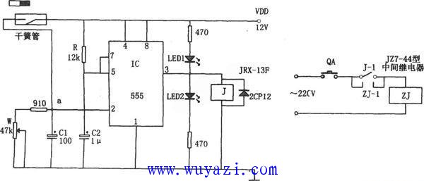
This circuit is designed to detect faults in a hoist system, specifically when the driven wheel slows down due to overload or loose drive pulley. The alarm system consists of a sensor, a 555 monostable multivibrator, and an alert mechanism. The sensor is a reed switch activated by a permanent magnet attached to the driven wheel. When the wheel rotates normally, the reed switch closes, allowing capacitor C1 to charge with each revolution. A potentiometer (W1) is used to adjust the charging voltage of C1 slightly above 1/3 of VDD, keeping the output of the 555 IC low, which illuminates LED 1. However, if the driven wheel slows down due to a fault, the discharge time of C1 increases, causing its voltage to drop below 1/3 VDD. This triggers the 555 IC to switch its output high, activating a relay (J). The relay then controls the intermediate relay system, signaling the fault condition. At the same time, LED 2 lights up to indicate the malfunction. This design leverages the relationship between the 555’s trigger level and the RC time constant, making it effective for detecting abnormal speeds in hoist operations. The circuit provides a reliable and cost-effective solution for monitoring hoist performance. It uses simple components like the NE555 IC, resistors, capacitors, and a reed switch, making it easy to implement and maintain. By adjusting the timing components, the system can be customized for different applications and speed thresholds. This type of alarm system is particularly useful in industrial settings where hoist reliability is critical to safety and operational efficiency. Flower Shape Mobile Phone Holder Flower Shape Mobile Phone Holder,Flower Shape Phone Socket Holder,Universal Phone Stand,Universal Phone Sockets Shenzhen Ruidian Technology CO., Ltd , https://www.wisonen.com