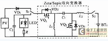
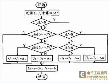
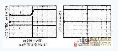
In order to solve the problems caused by the separate setting of the battery charging circuit and the LED driving circuit in the traditional design, this paper designs an independent photovoltaic LED lighting system based on Zeta/Sepic bidirectional converter. This paper proposes a charging control algorithm that not only realizes the MPPT of solar cells, but also satisfies the battery voltage limiting conditions and floating charging characteristics. An LED constant current driving circuit is designed. The Sepic converter is used as the main circuit, and the high-bright LED driver chip HV9930 is used as the control chip to ensure reliable and stable operation of the LED lighting equipment. 1 Introduction Solar energy is a huge, endless, clean green energy source. LED is also an environmentally friendly, energy-saving and efficient solid-state electric light source. It is the best energy-saving and environmental protection combination. The independent photovoltaic LED lighting system mainly consists of a photovoltaic cell array, a battery, an LED lighting device, a charging circuit, an LED driving circuit and a controller. Photovoltaic panels are the most expensive components of the whole system. In order to effectively use solar energy, MPPT is required for the system; the battery is the most vulnerable component of the system. In order to extend the battery life, the battery needs to be charged and discharged according to the characteristics of the battery; A certain driving circuit can ensure the reliable operation of the LED lighting equipment; all the above control functions are realized by the controller. 2 system components The conventional photovoltaic LED lighting system DC/DC conversion circuit and LED constant current driving circuit are two relatively independent circuit structures, and the system has the disadvantages of complicated structure, poor reliability and low efficiency. The two parts of the circuit principle and structure are very similar, and the charging and discharging of the photovoltaic LED lighting system will not be carried out at the same time. If the bidirectional converter is introduced into the system, the circuit structure can be simplified, the system performance can be improved, and the system efficiency can be improved. However, if a single-step converter with a single step-up or step-down function is used, the range and flexibility of the system will be reduced, especially in the case where the irradiance is weakened or the battery power is reduced, the operation of the LED lighting circuit cannot be well satisfied. . Here we design an independent photovoltaic LED lighting system based on Zeta/Sepic bidirectional converter. Its structure is shown in Figure 1. The charge and discharge circuit uses a bidirectional Zeta/Sepic converter, which allows flexible switching between the photovoltaic cell and the LED load. In the charging mode, the system switches the transfer switch to the photovoltaic cell, and the electric energy is charged to the battery through the bidirectional converter. The converter mainly completes the photovoltaic power generation MPPT control and the battery charging management; in the discharge mode, the transfer switch is switched to the LED lighting load, the battery The electric energy is supplied to the load through the bidirectional converter, and the converter mainly performs discharge management and LED constant current driving. Zeta/Sepic bidirectional converter and its application circuit in photovoltaic LED lighting system are shown in Figure 2. By adding relay switches S1, S2, the circuit structure is more suitable for photovoltaic LED lighting systems without adding power electronics. S1 mainly completes the switching control between the photovoltaic cell and the LED lighting load; S2 mainly acts as an isolation protection. When the main circuit fails or the battery is abnormal, the connection between the battery and the main circuit is quickly cut off, which increases the reliability and flexibility of the system. 3 charging control 3.1 Charging circuit In the charging mode of operation, the circuit topology is a Zeta converter. If the circuit enters steady state, when VQ1 is turned on, the photovoltaic cell stores energy to V1 through VD1, and supplies power to the battery through C1 and L2. When VQ1 is turned off, L1 charges C1 through VD3, and L2 supplies power to the battery. The input and output voltage relationship of the Zeta converter is: Uo=DUi/(1-D). Since the load of the Zeta converter is the battery, the value of Uo will be clamped to the voltage U across the battery, then Ui is determined by the duty cycle D of VQ1. By adjusting D, the voltage value of the maximum power point (MPP) of the photovoltaic array can be found. Um and current value Im. At this time, the photovoltaic cell charges the battery at maximum power. 3.2 Charging algorithm For a battery, the most ideal charging method is three-stage charging method, namely constant current, constant voltage, and floating charge. For the photovoltaic LED lighting system, the night battery supplies power to the lighting load and the control circuit is always powered by the battery. When the solar battery is detected to meet the power supply condition, the battery is always in a state of non-full state when the DC/DC conversion circuit starts to work. Less than the maximum voltage limit UM of the battery, ie U 3.3 Algorithm Implementation 3.3.1 MPPT charging implementation The conductance increment method is based on the fact that the PU curve of the photovoltaic array is a one-order continuous guideable single-peak curve, and the first derivative is used to obtain the extremum method, that is, the total derivative is obtained for P=UI, and: dP=IdU+UdI The two sides are simultaneously divided by dU, and dP/dU=0, which can be obtained: dI/dU=-I/U, which is the condition that is required to reach the photovoltaic array MPP. The method determines the direction of the reference voltage change by comparing the magnitude of the output conductance change with the instantaneous conductance value. The flow chart of the conductance increment method is shown in Figure 3. Un, In is the sampled value, Un-1, In-1 is the last sampled value, dU=0, and the dI=0 condition often uses a small threshold instead of zero in actual use. 3.3.2 Constant voltage and floating charge implementation From the above analysis, both CV and VF provide a fixed voltage value to the battery. There are two ways to achieve this: 1 If the system accuracy is not high, just provide a fixed duty cycle to the Zeta circuit; 2 if the system accuracy High requirements can be achieved by feedback. In order to reduce the complexity of the system and improve the reliability, the first implementation method is selected here. 4 discharge design In the discharge mode of operation, the battery supplies power to the LED, and the battery supplies power to the LED load through the Sepic converter. The circuit works in current continuous mode (CCM). When VQ2 is on, the battery stores energy to L2, C1 and L1 circuits conduct, C2 supplies power to LED load; when VQ2 turns off, battery passes L2, C1 and VD2 backward LED The load is powered, and the L2, C1, and L1 circuits are turned on. Due to the nonlinearity of the LED characteristic curve and sensitivity to temperature, it must be powered by a constant current source. Based on the Sepic converter, current closed-loop control is used to achieve constant current driving of the LED lighting load. The high-brightness LED driver chip HV9930 is used as the control chip LED constant current driving circuit. 5 experiment debugging 5.1 System Capacity The solar cell adopts Solar HQ070P-90W panel. Under the standard test conditions (irradiance 1 kW/m2, temperature 25 °C), the basic parameters are: maximum power Pm=90 W, Um= 17.2 V, Im=5.23 A Open circuit voltage Uoc=21.6 V, short circuit current Isc=5.81 A. Photovoltaic LED lighting system source is 36 cost-effective white LED with rated power of 1 W and rated current of 300 mA, using 6 series 6 and mixed mode Connected and driven in a constant current mode. The LED lighting system energy storage device selects the valve-regulated sealed lead-acid battery. The larger the design capacity is, the more the work is in the shallow cycle, the longer the life, but the cost is relatively high, and the actual installation should be selected as appropriate. Here, the rated voltage of the battery is 12 V. The design capacity is still working when it is raining for 4 consecutive days. The appropriate parameters are selected for calculation and a certain margin is reserved. The battery capacity is finally selected to be 250 Ah. 5.2 Experimental data Using the above calculation parameters, select ATMEGA16 as the system control core, build the experimental system, and use the whole day with strong illumination as the test object. The experimental waveform is shown in Figure 4. Figure 4a shows the output voltage and current waveform of the photovoltaic cell when the light is abrupt in the MPPT algorithm charging mode. Figure 4b shows the current waveform of the LED driver circuit when the battery voltage drops in the discharge mode. For the typical test time, the charging modes adopted by the system are: 9:00~15:00, the charging mode is MPPT; at 16:00, the charging mode is CV; at 17:00, the charging mode is VF, the initial battery The state of charge SOC is 70%. The data pairs of the MPPT algorithm and the CV algorithm are shown in Table 1. Since U is basically the same, only the two algorithm charging currents are listed in the table, and the listed hourly time data is actually the average over time. The data shows that the utilization of the MPPT algorithm is increased by 15.85% compared with the CV algorithm. The goal of the photovoltaic LED constant current drive circuit is to keep the current flowing through the LED branch constant when U or ambient temperature changes. As can be seen from Fig. 4, when U drops, the branch current flowing through the LED is approximately a straight line, and almost no ripple exists. Further tests show that there is no significant change in the output current when U rises or the ambient temperature changes, indicating that the design of the drive circuit has a good constant current effect. 6 Conclusion The experimental system was constructed based on the calculation parameters. Tests show that the charge controller can accurately switch between MPPT, constant voltage and floating charge algorithms according to the state of the battery. The charging efficiency of MPPT charge is about 16% higher than that of constant voltage charge. The LED drive circuit can overcome the battery voltage and ambient temperature. Change to keep the output current constant. In short, the designed photovoltaic LED lighting system controller realizes the effective use of solar energy, prolongs the service life of the battery and ensures reliable and stable operation of the LED. Outdoor String Light Outdoor Led String Lights,Best Outdoor String Lights,Outdoor Solar String Lights,Outdoor Party Lights DONGGUAN JIANXING LIGHTING ELECTRIC APPLIANCES CO., LTD , https://www.rslightstring.com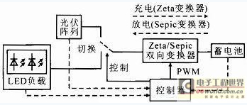

Outdoor String Light set is waterproof and durable.
Can be used in any season and many applications such as wedding, party,
garden etc. We have different wire model and Replacement Bulb type to
choose.
Decorative string
lights are not just for holidays anymore . Instantly transform indoor
and outdoor spaces with a wide selection of covers and finishes that match current trends and personal tastes and expressions.
Celebrate any season ,event or inspired whim with a charming new set of outdoor string lights!

Independent photovoltaic LED lighting system design based on bidirectional converter
0 times
Window._bd_share_config = { "common": { "bdSnsKey": {}, "bdText": "", "bdMini": "2", "bdMiniList": false, "bdPic": "", "bdStyle": " 0", "bdSize": "24" }, "share": {}, "image": { "viewList": ["qzone", "tsina", "tqq", "renren", "weixin"], "viewText": "Share to:", "viewSize": "16" }, "selectShare": { "bdContainerClass": null, "bdSelectMiniList": ["qzone", "tsina", "tqq", "renren" , "weixin"] } }; with (document) 0[(getElementsByTagName('head')[0] || body).appendChild(createElement('script')).src = 'http://bdimg.share. Baidu.com/static/api/js/share.js?v=89860593.js?cdnversion=' + ~(-new Date() / 36e5)];